Trip SP 1
The trip parameter can be set for either
High
or
Lo
When set to high, the open collector transistor stops conducting and sends
the output high when the setpoint is reached The output will not go low again until the flow rate falls below the setpoint
minus the hysteresis value When set to low, the open collector transistor starts conducting and sends the output low when
the setpoint is reached The output will not go high again until the flow rate exceeds the setpoint plus the hysteresis value
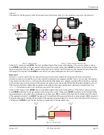
For example, if the set point is 10 gpm, the hysteresis is set to 2 gpm and the trip setpoint is set to
High
(see
) When
the flow goes above 10 gpm the OC transistor stops conducting and the output goes high The output stays high until the
flow rate drops below 8 gpm which is the setpoint (10 gpm) minus the hysteresis (2 gpm)
Minimum
Flow
Maximum
Flow
Output ON
OFF (8 g
pm)
Setpoin
t (10 g
pm)
Hysteresis
(2 gpm)
Output OFF
Figure 15: Setpoint example
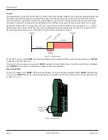
At the
TripSP1
prompt, press
ENTER
The tripping condition setting is displayed If the current setting is correct, press
ENTER
to advance to the next parameter
If the current setting requires a change, press
RIGHT
to advance to the alternate choice Once the correct choice is displayed,
press
ENTER
to save the new trip condition and advance to the next parameter
Clear Grand Total*
At the
Clr G-T
prompt, press
ENTER
The flow monitor displays
No
To clear the grand total press,
UP
or
RIGHT
to change from
No
to
Yes
Press
ENTER
to select
Yes
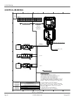
and advance to the next parameter The totalizer can also be reset using a hardware reset
as shown in
JP1
JP2
JP3
Input
Total P
ulse
Sig
nal
P1
Freq. In
4-20mA
Iso Total Pluse
TR_B
TR_A
RS485 Gnd
Setpoint 1
Setpoint 2
Gnd
+
–
+
–
+
–
Total Reset
OC Total Pluse
Signal Gnd
TB1
Mag
Pulse
Iso
OC
Low
High
Normally Open
Pushbutton
Switch
Figure 16: Hardware reset
Programming
DSY-PM-00028-EN-02
Page 24
February 2017
Summary of Contents for ER-500
Page 1: ...Display ER 500 Advanced DSY PM 00028 EN 02 February 2017 Programming Manual...
Page 2: ...ER 500 Flow Monitor Page ii February 2017 DSY PM 00028 EN 02...
Page 4: ...ER 500 Flow Monitor Page iv February 2017 DSY PM 00028 EN 02...
Page 34: ...Display ER 500 Advanced INTENTIONAL BLANK PAGE DSY PM 00028 EN 02 Page 34 February 2017...
Page 35: ...Programming Manual INTENTIONAL BLANK PAGE DSY PM 00028 EN 02 Page 35 February 2017...


