Symptoms
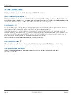
Symptom: Transmitter does not power up.
Possible Causes
Recommended Action
• No power or inadequate power
• Blown fuse (AC Model only)
• Display ribbon cable not seated
properly
• Measure voltage at the power terminals and check that the voltage matches the labels by the
power terminals
• Check the fuse near the power terminals If fuse is blown, verify the voltage and polarity is
correct and reset the fuse
• Inspect ribbon cable connections LED’s on power board will light up with no LCD display
• Replace the transmitter if the above actions do not resolve the issue
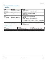
Symptom: Flow reading appears to be incorrect.
Possible Causes
Recommended Action
• Incorrect positioning of
transducers
• Poor contact between
transducers and pipe
• Poor placement of transducers
• Low signal strength
• Process loop issues
• Incorrect pipe settings
• Meter not calibrated?
• Display not set up correctly
Refer to the Transducer Mounting Configuration section for details on proper installation
At the transducer:
• Verify that the spacing of the transducers is set correctly On most transducers, a scribe mark on
the side of the transducers indicates the point of measurement—NOT from the end points of
the transducers
• Verify that the transducers are aligned correctly For Z-Mount, verify the transducers are 180°
from each other
• Make sure there is a good contact between the transducers and pipe and a thin coat of acoustic
coupling is applied For integral mount, check for over-tightening of the transducers
Process loop and general location:
• Make sure the transducers are on the sides of the pipe and NOT on the top of the pipe
• Check that the transducers are NOT located at the highest point in the loop where air may
accumulate
• Check that the transducers are NOT on a downward flowing pipe unless adequate downstream
head pressure is present to overcome partial filling or cavitation
• Check that the transducers have adequate straight pipe upstream and downstream
• Check process loop for entrained air or particulates which will impact the flow readings
• Pipes may develop scale, product build-up or corrosion over time As a result, the effective wall
thickness may be different than a new pipe and wall thickness or liner parameters may need to
be adjusted
At the transmitter:
• Verify that pipe parameters match the installation
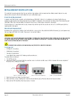
Symptom: Unstable flow.
Possible Causes
Recommended Action
• Installation issues
• Flow instability
• Transducers mounting is loose
• Transducers are moved
• Check process loop for variations of entrained air which will impact the flow
• Check for pump induced flow instability
• Check that the transducers are secure and are in area where the transducers will not be
inadvertently bumped or disturbed
Symptom: Flow readout is opposite of the flow direction.
Possible Causes
Recommended Action
• Integral mount transmitter
is mounted in reverse flow
direction so display is properly
oriented
• Up and down transducers wiring
reversed
• Flow direction parameter is
reversed
• Change the transducer flow direction parameter
• Rewire the up and down transducers to the transmitter
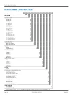
Symptoms: Current, frequency or pulse outputs do not match the readings.
Possible Causes
Recommended Action
• Incorrect parameter settings
• Wiring or control system
configuration issues
Verify that the parameters for the output are set properly
Troubleshooting
Page 35
May 2021
TTM-UM-02537-EN-06


