10
© Copyright 2012 Badger Fire Protection
4 If internal cylinder examination is required, fully discharge and depressurize cylinder to per-
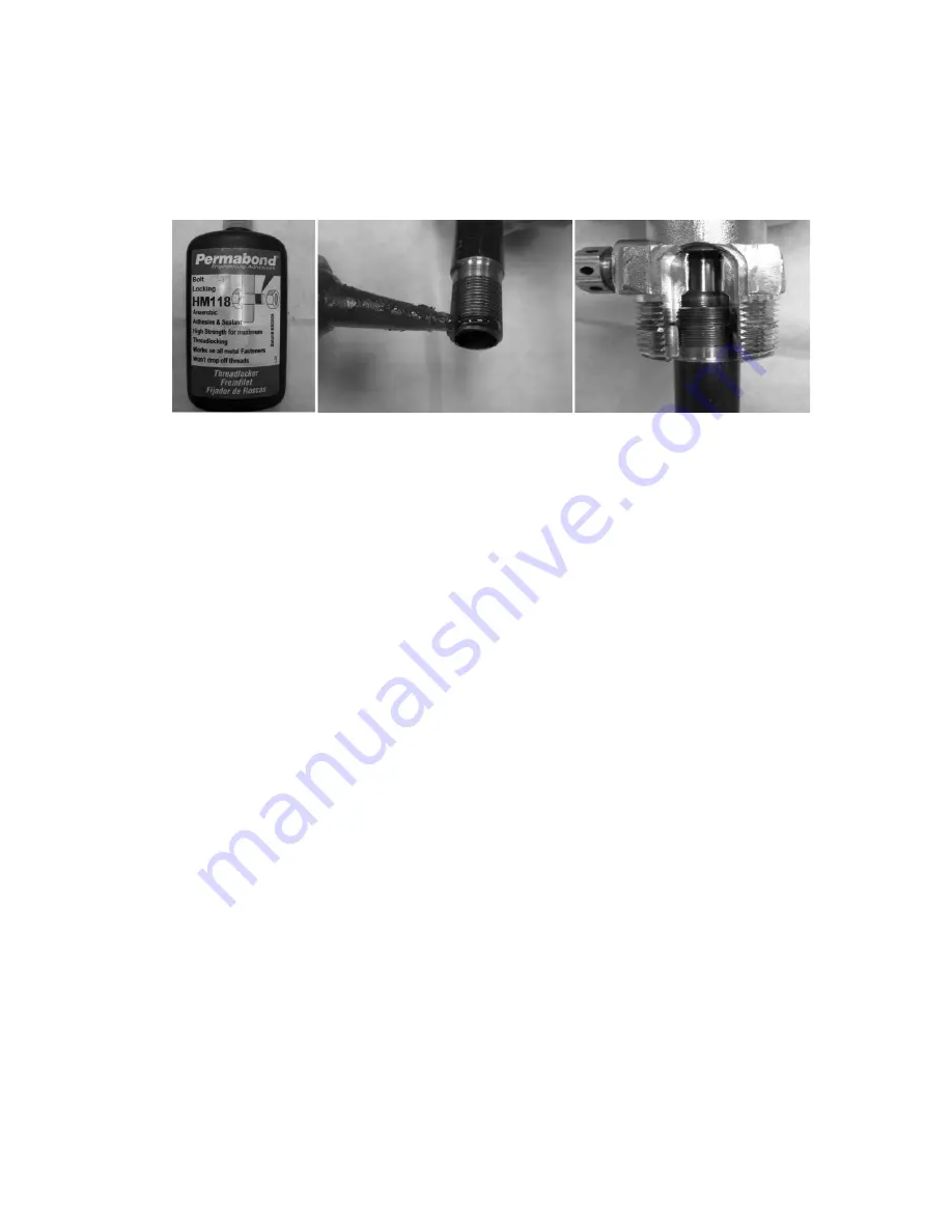
mit proper removal of valve assembly Proper installation of siphon tubes require examination
of both threaded surfaces to ensure they are clean and undamaged Prior to installation, a
light uniform bead of Permabond HM 118 should be carefully applied around the 2nd and 3rd
threads of the siphon tube, so that no sealant can enter the siphon tube Screw siphon tube into
the valve assembly hand tight till it bottoms out and then tighten an additional ¼ turn with a
small pipe wrench No exposed threads or gaps should be visible
5 Closely examine the agent cylinder for any signs of damage, wear, dents, corrosion or repair
6 The periodic re-hydrostatic test date of the extinguisher cylinder must be checked prior to
recharge The maximum periodic interval for Badger carbon dioxide wheeled fire extinguishers is
5 years (Refer to CFR-49 for specific cylinder hydrostatic test requirements and procedures )
7 Ensure the extinguisher operating nameplate instructions are secure and legible Check to
ensure HMIS information is present and legible
8 Unthread and remove the agent hose assembly from the cylinder discharge valve assembly
9 Visually examine the cylinder valve discharge port for any signs of thread wear, corrosion,
obstructions or accumulations of any foreign material Ensure the anti-recoil device is properly
installed
10 Examine the cylinder valve safety relief assembly to ensure it is not damaged, corroded or
obstructed
Note: If replacement of safety relief is required, the extinguisher must first be emptied
and free of any pressure. A new Badger 3 part safety assembly (P/N-24643)) should be
installed washer first, then the disc (printed side outward) and then the nut. The new
safety assembly must be properly torqued between 30 to 35 foot-pounds.
11 Install the proper CO2 cylinder “safety shipping cap” securely onto the valve for handling and
transportation Loosen the frame retainer clamp and remove the cylinder from the extinguisher
frame for filling
12 Using a calibrated weight scale to determine the proper agent charge, the cylinder can be filled
Install the proper carbon dioxide charge adapter into the cylinder valve outlet port Slowly ro-
tate the extinguisher valve hand wheel operating lever and properly fill the cylinder to the
fully charged weight stamped on the cylinder valve
NOTE: When filling extinguishers from a carbon dioxide supply utilizing a pump, the
specific instructions for using that equipment should be followed. Ensure the carbon
dioxide supply meets the extinguishing agent specifications identified earlier in this
manual for recharging Badger fire extinguishers.


