background image

RECOMMENDED MAINTENANCE AND MONITORING PROGRAMME

www.BaltimoreAircoil.com
[email protected]

Baltimore Aircoil Company SA
(Pty) Ltd.
Portland Road, Phillipi
Cape Town, South Africa

©

Baltimore Aircoil Company SA (Pty) Ltd

Model: ...........................................................................................

Serial number: .................................................................................

* only for motors with grease fittings 
** depends on applied code of practice
Notes:
1. Water Treatment and auxiliary equipment integrated in the cooling system may require additions to the table above. Contact suppliers for

recommended actions and their required frequency.

2. Recommended service intervals are for typical installations. Different environmental conditions may dictate more frequent servicing.
3. For units with Belt Drive, tension on new belts must be readjusted after the first 24 hours of operation and monthly thereafter.
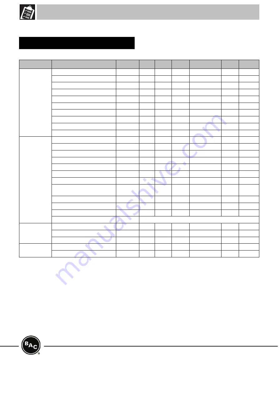
Schedule

Type of Action

Action

Start-Up

Weekly Monthly Quarterly Every Six Months Annually Shutdown

Checks and 
Adjustments

Cold Water Basin and Strainers

X

X

Operating level and make-up

X

X

Blow down

X

X

Sump heater package

X

X

Belt tension

X

X

Drive alignment

X

X

Locking Collar

X

X

Rotation of fan(s) and pump(s)

X

Motor voltage and current

X

X

Unusual noise and/or vibration

X

X

Inspections and 
Monitoring

General condition

X

X

Heat transfer section

X

X

Finned discharge coil (optional)

X

X

Drift eliminators

X

X

Water distribution

X

X

Fan Shaft

X

X

Fan Motor

X

X

Electric Water Level Control Package 
(optional)

X

X

TAB test (dip slides)

X

X

Circulating water quality

X

X

System overview

X

X

Record keeping

as per event

Lubrication

Fan shaft bearings

X

X

Motor bearings *

X

X

Adjustable motor base

X

X

Cleaning 
procedures

Mechanical cleaning

X

X

Disinfection **

(X)

(X)

(X)

Table 4: Recommended Maintenance & Monitoring Schedule

Summary of Contents for VCL

Page 1: ...nd to assure that all necessary equipment will be available at the jobsite Be sure to have a copy of the unit certified drawing available for reference If you do not have a copy of this drawing or if you need additional information about this unit contact the local BAC representative The model number and serial number of the unit are located on a label on the sinde of the unit Table of Contents Pa...

Page 2: ... suggested support details on the certified drawing for locations of the mounting holes Anchor bolts must be provided by others Holes suitable for 20 mm bolts are provided in the bottom flange of the lower section for bolting the unit to the support beams The unit must be level for proper operation and ease of piping Support beams must also be level as shims should not be used between pan and supp...

Page 3: ...ens access panels and access doors in place When the equipment is operated with a variable fan speed control device steps must be taken to avoid operating at or near to the fan s critical speed For more information consult your local BAC Balticare representative ELECTRICAL SAFETY Each fan and pump motor associated with this equipment should be installed with a lockable disconnect switch located wi...

Page 4: ...ng shorten the slings at one end so the casing is approximately horizontal General Notes COOLING TOWERS VTL Model N Minimum H mm Spreader Bar Length mm Discharge Accessory1 Minimum H VTL 039 to VTL 079 3100 1250 3100 VTL 076 to VTL 095 4300 1250 4300 VTL 089 to VTL 137 5000 1250 5000 VTL 139 to VTL 227 4300 2450 4300 VTL 225 to VTL 272 5000 2450 5000 Table 1 Rigging method VTL and discharge access...

Page 5: ...ges of the upper section are about 50 mm above the lower section Dot not let the upper section swing and damage the sealer Using at least four drift pins see figure in the fastening holes located on the long sides of the sections to align the top section to the bottom section To avoid incorrect alignment refer to the below drawing for the position of the fastening holes to be used Use additional d...

Page 6: ...es of the clean out port are mounted with flanges towards the inside 1 On site the cover can be placed with flanges to the outside for easy access to hardware 2 Clean out port Figure 5 Clean out port cover mounted for transport Figure 6 Final installation of clean out port cover ...

Page 7: ...he Operating and Maintenance Manual see Table Recommended Maintenance and Monitoring Schedule Start up must be performed Proper start up procedures and scheduled periodic maintenance will prolong the life of the equipment and ensure trouble free performance for which the unit is designed Start up Inspection ...

Page 8: ...eration and monthly thereafter Schedule Type of Action Action Start Up Weekly Monthly Quarterly Every Six Months Annually Shutdown Checks and Adjustments Cold Water Basin and Strainers X X Operating level and make up X X Blow down X X Sump heater package X X Belt tension X X Drive alignment X X Locking Collar X X Rotation of fan s and pump s X Motor voltage and current X X Unusual noise and or vib...

Reviews: