background image


 ULTRAGRIND  PG. 7

4. Transport wheel can be turned so wheel is 

in the up position & installed into bracket 

for storage; make sure the locking pin is 

securely engaged. The transport wheel may 

also be stored separate from the machine.

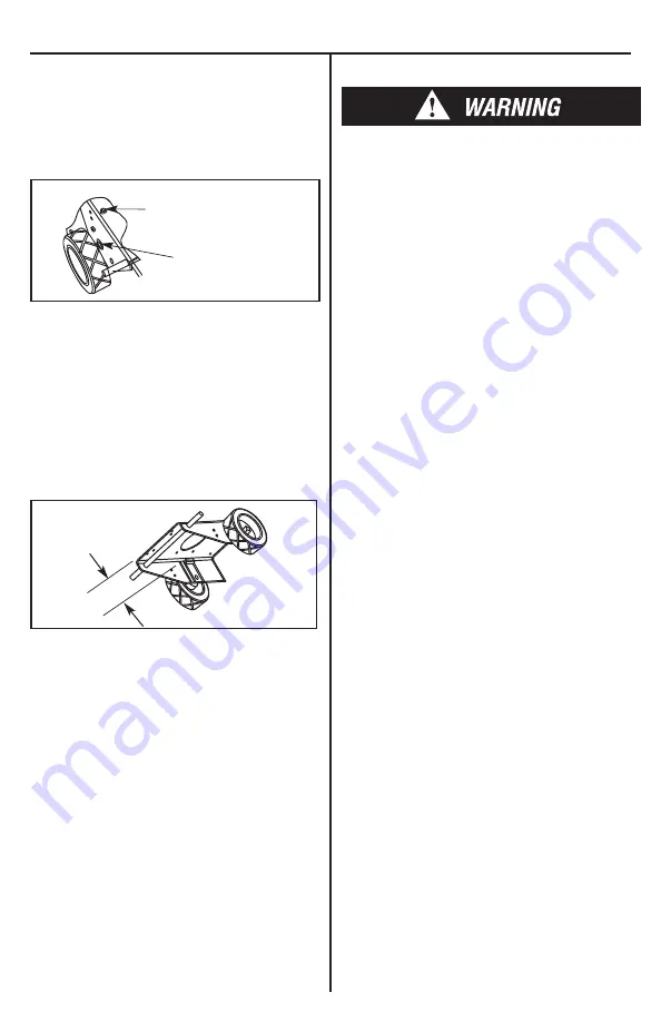
d. Wheel adjustment

Turn clockwise to lower
Turn counter-clockwise
to raise

Loosen 1/2-13 bolt

Wheel adjustment must be made to both wheels 

on level floor.

1. Loosen 1/2-13 x 1 1/4” bolt 
2. Loosen 1/2-13 jam nut just above axle bracket
3. Adjust machine height by turning the 

1/2-13 x 5” bolt counter clockwise to raise 

machine or clockwise to lower machine

4. Tighten 1/2-13 jam nut
5. Tighten 1/2-13 x 1 1/4” bolt

e. Rear Wheel setting

GAP

Gap factory setting is 2”. Set gap as shown in 

diagram.
f. installing the fuel Cylinder

1. Take UltraGrind to well ventilated area
2. Check cylinder for overfill
3. Place cylinder on the machine in tank 

holding area and secure the safety strap

4. Connect fuel cylinder to the machine, 

tighten hand tight. Do not use a wrench or 

pliers or cross thread

5. Open the service valve slowly, be alert for the 

odor of propane which may indicate a leak

6. To remove the cylinder, reverse the procedure

G. Before operating the UltraGrind

• Check oil level 

• Check carburetor air filter 

• Check diamonds and diamond plates 

• Adjust handle height 

• Install fuel cylinder in a well ventilated area 

H. Before you start the engine

do not allow machine to come into contact with 
loose tiles or other obstructions on the floor. 
the abrasives will be turning at approximately 
650 Rpm. if objects are hit, they could become 
dangerous projectiles!

• Extend the handle and tilt machine back until 

handle rests on floor. 

• Install diamonds and remove transport wheel.
• Bring machine back to operating position.
• Fill water tank if wet grinding.

i. preparing to start the engine

1. First - check fuel cylinder for overfill and 

install cylinder onto machine.

2. Place machine on level surface and check 

for correct oil level.

3. Attach lanyard kill switch clip to the operator.  

The lanyard kill switch is a safety switch used 

 if the operator would fall or lose control of 

the  machine; the lanyard will pull away from 

the  switch and kill the engine. The lanyard 

must be  securely fastened to the operator 

with the attached  clip fastener. If the lanyard 

should become  disengaged from the switch, 

it can simply be  reattached to the switch 

and engine can be restarted.  The lanyard 

kill switch, when activated, will ground  the 

ignition coils, resulting in no spark to the 

spark  plugs, stopping the engine. If the 

lanyard should become  disengaged from the 

switch and the machine is no  longer going to 

be used, the tank valve must be closed  and 

the ignition key turned to the off position.

J. transporting the machine

1. The tank should be securely fastened.
2. The tank valve must be closed.

staRtinG tHe enGine 

1. Open propane (LPG) tank valve (counter 

clockwise).

2. Turn the key to start position and move 

throttle towards fast position.

3. If engine does not start, release the key, 

then try again.

4. Equipment is supplied with a centrifugal  

clutch. When engine RPM is lower than 1800 

RPM clutch will disengage; drivers will stop.

Summary of Contents for ULTRAGRIND

Page 1: ...Kawasaki 603cc Engine Meets U S Green Building Council LEED IEQ Credit 3 4 Requirements CE LEED CARB EPA GS 42 Compliant 201 COMMERCE DRIVE MONTGOMERYVILLE PA 18936 215 393 4700 800 331 1423 FAX 215...

Page 2: ...rce where possible In this regard use good work practices and follow the recommendations of the manufacturers or suppliers OSHA NIOSH and occupational and trade associations Water should be used for d...

Page 3: ...lt in death Never change or alter the propane control components This machine is factory equipped with engine components and emission controls that maintain harmfulexhaustemissionsbelowcertifiedaccept...

Page 4: ...short periods of time such as rest stops washroom or meal stops The operator must completely understand all instructions warning and operating procedures before using this machine This machine must b...

Page 5: ...ions pg 9 B Check the engine oil before every operation Make sure the machine is level when checking the oil Always take 2 readings of the dipstick before adding oil If the oil level is below the full...

Page 6: ...Position B Plate Assembly and Diamond Installation Resin Bond Metal Bond with 3 Screws Metal Bond with 1 Screw Resin Bond 1 Close service valve on fuel cylinder to prevent liquid from getting into the...

Page 7: ...The abrasives will be turning at approximately 650 RPM If objects are hit they could become dangerous projectiles Extend the handle and tilt machine back until handle rests on floor Install diamonds...

Page 8: ...dry before replacing Failure to the engine filter clean may result in engine overheating Changing Gear Drive Lubricant After the first 100 hours of operation drain out initial oil flush out the gear c...

Page 9: ...machine and the LPG tank Never allow anyone to operate this machine who has not read or cannot understand the given instructions G Troubleshooting the electrical system 1 Check all wire connections fo...

Page 10: ...SCREWING IT IN Remove the oil gauge to check the oil level The oil level should be between ADD and FULL marks Do not overfill Install and tighten the oil gauge Recommended Oils The following engine oi...

Page 11: ...recycling WARNING KAWASAKI ENGINE MAINTENANCE SCHEDULE INTERVAL MAINTENANCE Daily First 8 hr Every 25 Hr Every 50 hr Every 100 hr Every 200 hr Every 300 hr Lubricate Pillow Block Bearings Check and a...

Page 12: ...ery Loose or faulty connections or wires Tighten repair or replace wires Faulty ignition key switch or starter control switch Repair or replace switch es Engine overheats Incorrect fuel settings Have...

Page 13: ...ULTRAGRIND PG 13 Warning Label Locations Model The Ultragrind Propane Powered Grinder Wear approved respiratory protection when the machine is operating...

Page 14: ...LPG tank 1 is filled connected and checked for leaks See Pg 3 4 Open the LPG tank by turning the knob 2 anti clockwise 5 Set throttle lever 3 to idle position 6 Turn key 4 to start position 7 Move th...

Page 15: ...PLATE 283 040 900L 1 5 VACUUM CAPS 040 3015 2 6 WHEEL BASE BRACKET 288 040 10 1 7 TRANSPORT WHEEL BRACKET 288 040 2300 1 8 TRANSPORT WHEEL 156 040 1 1 9 BELT COVER 288 040 300 1 10 LEFT SHIELD 288 040...

Page 16: ...OX BOTTOM 283 11 2127B 1 5 BATTERY 12V 276 GTX14 1 6 BATTERY BOX TOP 283 11 2127T 1 7 QUICK RELEASE PIN 625 97320A760 2 8 KEY SWITCH 312 308 0385 1 9 LANYARD KILL SWITCH 153 73459 1 10 HANDLE EXTENSIO...

Page 17: ...5 3 8 16 X 1 HCS 164 10115 8 6 5 16 FLAT WASHER 164 20156 16 7 3 8 16 STOVER LOCK NUT 164 22834 8 8 1 2 13 X 5 TAP BOLT 164 50C500BTA52 2 9 1 2 FLAT WASHER 164 20159 4 10 1 2 13 STOVER LOCK NUT 164 2...

Page 18: ...FLAT WASHER 164 20159 8 4 BELT 113 L548 1 5 1 2 13 X 2 HCS 164 110120382 4 6 BELT TENSIONER 011 6 2795 1 7 1 2 13 X 11 4 FSCS 164 50C125KFC 4 8 7 16 20 X 1 HCS 164 10301 1 9 WASHER 164 20164 1 10 DRI...

Page 19: ...CS 164 10117 SS 1 16 SHAFT END PLATE 283 040 2235 1 17 1 4 KEY 199 NHNT SE UND 1 18 DRIVE PLATE ASSEMBLY 040 2255 3 19 SHAFT SEAL 040 4000 3 DIAMOND DRIVERS PARTS PART DESCRIPTION PART QTY 1 Foam Hat...

Page 20: ...ustomer must call Aztec Products Inc for an RGA Return Goods Authorization Number 2 We maintain the serial number date of shipment or sale and customer name on each piece of equipment sold If you were...

Reviews: