Section 9 - 3
Azalea Aviation Copyright 2014
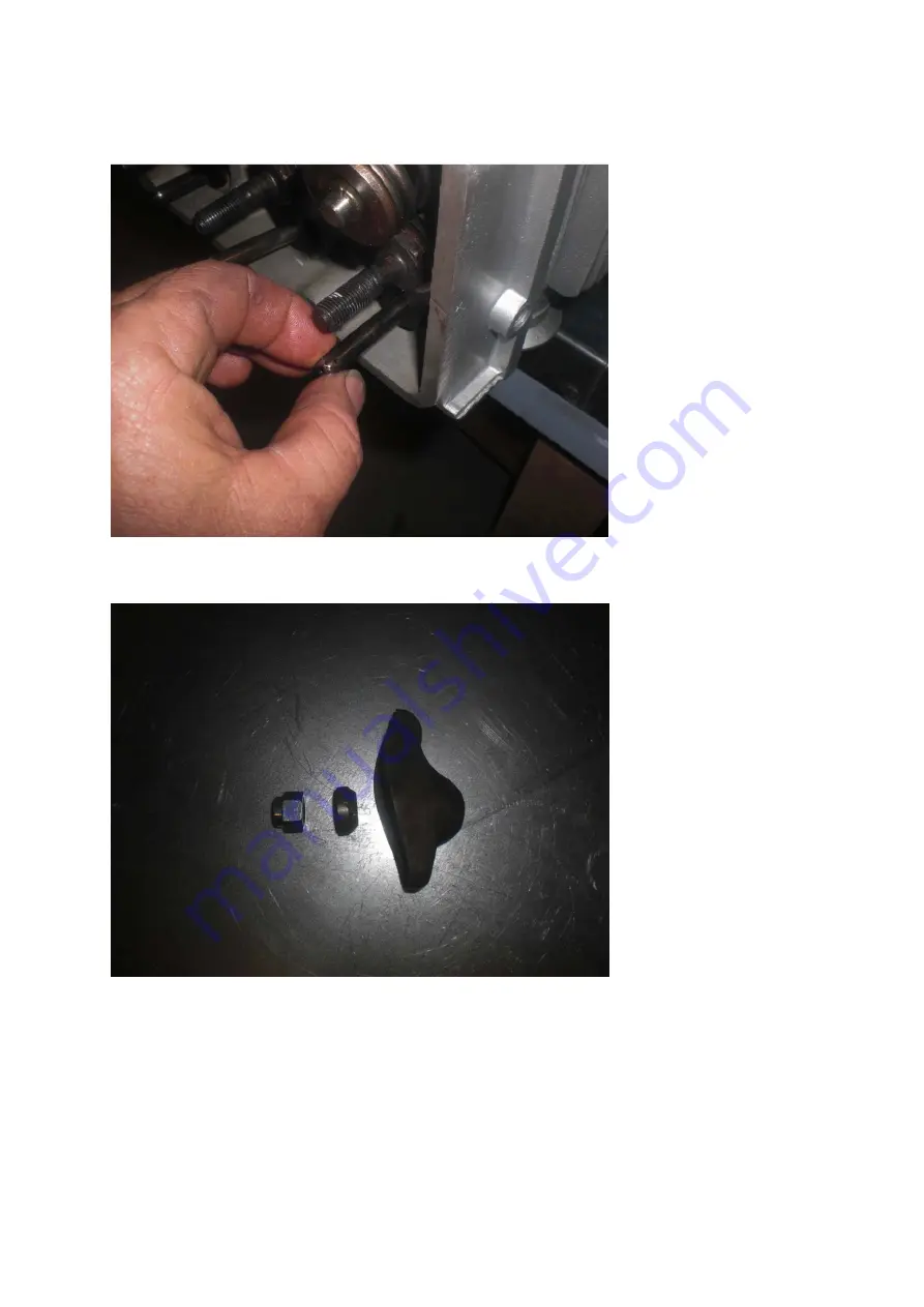
Fig. 1 – Inserting pushrod into guide plate
Fig. 2 – Rocker assembly
Page 1: ...AZALEAAVIATION LLC 100 120 ENGINE ASSEMBLY MANUAL AZALEAAVIATION LLC 100 120 HP SPYDER ENGINE ASSEMBLY MANUAL AzaleaAviation com HP SPYDER ENGINE ASSEMBLY MANUAL...
Page 2: ...Accessory Alternator Installation 5 Starter Oil Cover Plate Installation 6 Piston Cylinder Assembly 7 Piston Cylinder Final Installation 8 Cylinder Head Installation 9 Valve Train Assembly and Adjust...
Page 3: ...tact us or use several additional sources of information available The Chevrolet Green Shop Manual for 1965 Corvair and the SPYDER Service and Operations Manual can be helpful You can also contact the...
Page 4: ...and preparation finished Tools Required 3 16 Allen wrench Straight edge Feeler gauge 004 13 16 wrench Distributor shaft or Long screwdriver Sealants Required Grey RTV Loctite Lithium Grease Copper Spr...
Page 5: ...k up Spread a little bit of oil on the tops of the gears Make sure to leave the housing surface dry where the gasket will lay Fig 2 Apply a dab of loctite to the six Allen bolts and install the oil pu...
Page 6: ...Section 3 3 Azalea Aviation Copyright 2014 Fig 1 Checking clearance Fig 2 Installing Cover plate...
Page 7: ...ted with oil Using a screwdriver or small tube insert the piston into the port and make sure it has freedom of movement in the port If it sticks then clean the port and try again The piston has to mov...
Page 8: ...eal may have to be carefully trimmed around the outside edge to fit inside the stator ring Fig 5 Apply Lithium Grease to the inside of seal This will be where the alternator puck rides Fig 5 Rear Hous...
Page 9: ...ired Rubber hammer socket and Ratchet 9 16 Socket Large socket for gear installation Sealants Required Copper spray Loctite red and green Lithium Grease Parts Required Case assembly Drive gears 4 part...
Page 10: ...er Fig 1b Be sure the woodruff keys are installed properly onto the crankshaft prior to installation Fig 1 Rear gear parts installed on the crankshaft Fig 1b Housing Installation Apply an even coat of...
Page 11: ...on Use the Adel clamp and the short housing Allen head bolt to secure it Make sure the stator is flush against the stator mounting ring Figure 3 Fig 3 Stator attached and clamp detail Apply green slee...
Page 12: ...he ring gear and starter are installed Be sure the drum is clean on the inside Because it is made up of magnets it can attract small filings Notice that there may be a positioning pin on the puck and...
Page 13: ...3 16 Hex socket Torque wrench 17 mm wrench 9 16 socket Sealants Required Copper spray Pipe Sealant Red Loctite Parts Required Case with Rear Alternator attached Oil Cover Plate and hardware Starter R...
Page 14: ...tall the starter and check for fit Check the clearance on the ring gear to bendix gear on the starter Have at least a 1 8 space Adjustments can be made by placing a washer under the top starter bolt T...
Page 15: ...Section 5 3 Azalea Aviation Copyright 2014 Fig 2 Block Off Plate Installed Fig 3 Ring gear to Bendix clearance...
Page 16: ...4 Lower Bracket bolted in place Fig 5 Starter and Ring Gear Finally Bolted Be sure to rotate the crankshaft and check for clearance and interference Pulses felt during the rotation that is caused by t...
Page 17: ...rods 6 Set of New Forged Pistons 6 Fig 1 Tools and Parts Inspect condition and quality of parts Fig 1 Clamp the 1 Connecting rod in the vise with the numbers up Use wooden blocks or aluminum angles in...
Page 18: ...d so on Using the torch slowly heat up the small end of the rod until it starts to turn a light brownish color Fig 3 Quickly insert the piston in correct orientation and slide the wrist pin it until i...
Page 19: ...Section 6 3 Azalea Aviation Copyright 2014 Fig 3 Heating up Rod small end brownish color Fig 4 Inserting Rod pin using tool quickly and smoothly...
Page 20: ...ly 6 Piston Ring set Hastings Chrome Rebuilt cylinders or new 6 Inspect the condition and quality of all the parts for this step Be sure that the cylinders are matching the bore of the pistons and rin...
Page 21: ...y on the inside walls with oil Place the cylinder into position on the assembly tool Fig 3 The tool is marked as to direction of piston installation Place the piston assembly from the top resting the...
Page 22: ...Section 6 6 Azalea Aviation Copyright 2014 Fig 2 Rings installed Fig 3 Cylinder in alignment Fixture make your own or call Azalea Aviation for rental plans to build...
Page 23: ...Section 6 7 Azalea Aviation Copyright 2014 Fig 4 Install piston in correct orientation and compress rings Fig 5 Remove the wooden block and firmly tap the piston into cylinder...
Page 24: ...Section 6 8 Azalea Aviation Copyright 2014 Finished and ready for next step...
Page 25: ...quired Torque Wrench 3 8 12 point socket Wrench for turning crankshaft Sealants Copper spray Oil ARP grease Parts Required Case assembly Piston Cylinder assemblies 6 Connecting rod bearing kit Cylinde...
Page 26: ...distributor and work forward One method is to install the pistons and cylinder on one side and then use a head to hold the cylinders in position while installing the opposite side Begin by applying an...
Page 27: ...Section 7 3 Azalea Aviation Copyright 2014 Fig 3 Install rod bearing shell and copper base gasket on cylinder Fig 4 Oiling bearing shell...
Page 28: ...bar rotate the crankshaft back until the journal is flush into the rod bearing Fig 5 Take care to not let the rod bolts scratch the crankshaft journal Insert the rod cap into position on the rod and...
Page 29: ...se snap the cylinder baffle into position Insure that the clips are well secured around the studs Fig 8 Use a cylinder head to hold the cylinders in position temporarily while the other side is assemb...
Page 30: ...2014 Fig 8 Installation of Baffle and clips Notice the assembly board under the case to provide clearance for the camshaft gear Fig 9 Installing head loosely to check for smooth rotation of parts not...
Page 31: ...are of a different design Fig 1 They are new forged rods and due to the close clearances are installed into the case through the cylinder openings and torque before installing piston cylinder units Fi...
Page 32: ...ile installing Push the cylinder into the piston up to the wrist pin opening Because these are free floating wrist pins the snap ring will have to be installed on one side of the piston before install...
Page 33: ...12 Rocker base plates 6 Rocker Shaft bolts 12 New Rocker shaft seals 12 New Head nuts 12 New Head washers 12 Inspect all your parts for condition fit and wear Have a clean work station and tools befo...
Page 34: ...ndex finger and wipe the inside of the lifter bores Slide the lifters into lifter bores and seat against the camshaft Fig 3 do not prime the lifter The lifters are inserted with the flat against the c...
Page 35: ...y anti seize to head stud threads Insure that the gasket surfaces of the heads and cylinders are clean Insert the copper head gaskets into the cylinder bores Fig 5 and gently slide the head over the s...
Page 36: ...the pushrod tube bores on the head Prepare the rocker shaft plates by applying anti seize to the bottom side of the nut where it touches the plate Apply lithium grease to the o rings and slide them o...
Page 37: ...on the surfaces of the bores where the tubes are inserted Insert the tube into the hole on the head and then install the other o ring Fig 7 Insert the tube into the lifter bore Use the 9 16 socket to...
Page 38: ...move the head and check for obstruction Use the torque sequence and pattern to bring the head up to final torque Fig 9 Use the torque wrench in a steady and smooth motion Once it clicks hold that posi...
Page 39: ...Section 8 7 Azalea Aviation Copyright 2014 Heads are installed and torqued On to the valve train...
Page 40: ...Tools required 5 8 Deep Socket and ratchet 3 16 Allen wrench Socket and handle Sealants Oil Grey RTV Loctite Parts Required Pushrods 12 Rockers 12 Grooved balls 12 Rocker shaft nuts 12 Valve covers 2...
Page 41: ...o the guide plate where the pushrod makes contact Make sure the end of the pushrod with the small hole on the side is toward the heads and away from the lifter This hole squirts oil onto the rocker as...
Page 42: ...Section 9 3 Azalea Aviation Copyright 2014 Fig 1 Inserting pushrod into guide plate Fig 2 Rocker assembly...
Page 43: ...ing your socket and wrench on the starter end or prop hub tool and turn the engine direction of prop rotation clockwise until 1 piston is all the way up in the cylinder Use a flashlight look at the ca...
Page 44: ...s for cylinder 1 while slowly tightening the nut on the rocker with a 5 8 deep socket The pushrod should rotate freely until the rocker bottoms against the valve The pushrod will suddenly be harder to...
Page 45: ...o see that all the rocker shafts bolts show about the same number of threads past the nuts If one is obviously different check for misalignment of the pushrod or a rocker ball installed up side down A...
Page 46: ...Section 9 7 Azalea Aviation Copyright 2014 A 120 HP engine with valve train work finished and up on rotator stand...
Page 47: ...Permatex sealant Loctite Parts Required Oil Pan Oil Pan Hardware Oil Pan Gasket Oil Pickup 5 16 bolt and lock washer for pickup Dipstick and tube Check all parts for condition and quality There are a...
Page 48: ...tube check the diameter of the tube where it enter the case to be sure it is the correct size A small hole is drilled into the tube an inch or so from the sealing surface Fig 1 This hole is there to a...
Page 49: ...to 10 ft lbs Fig 3 There are a couple different styles of pickup tubes that will match the oil pan Installation is the same with all of them Fig 3 Typical oil pickup installation Oil Pan Installation...
Page 50: ...bolts Tighten the bolts around the oil pan slowly and evenly until 90 inch lbs is met Clean excess RTV from around the oil pan You can also use a razor blade to clean excess gasket material away from...
Page 51: ...ght 2014 Final Pan Installation This is showing our HD cast aluminum pan It allows you to place the engine on the ground without fear of damaging the pan Some pans are very lightweight and thin and wi...
Page 52: ...p Loosely install the top cover onto the engine in its correct orientation to protect the inside of the case If it will be some time before pre oiling and test running secure a couple of the allen scr...
Page 53: ...he case number located by the starter bracket Our production numbers are different You may also wish to paint or decorate polish the cover Once pre oiling is done clean the surface of the case and the...
Page 54: ...Section 11 3 Azalea Aviation LLC Copyright 2014 John finalizing his installation a good view of the oil line and top cover...
Page 55: ...Copyright 2014 Ignition Installation Tools Required 9 16 Wrench Sealants Oil Parts Required Distributor aviation ready Distributor gasket Distributor Hold Down Clamp 3 8 24 Self locking nut Check all...
Page 56: ...tion As the gears mesh the rotor will turn slightly to the 10 o clock position If the distributor does not seat all the way rotate the crankshaft slowly until the distributor shaft drops into the oil...
Page 57: ...ay by hand Never use a wrench to start spark plugs as the danger of cross threading is real high Torque the plugs to the rated torque The firing order of the Engine is marked on our top covers It is 1...
Page 58: ...Section 12 4 Azalea Aviation LLC Copyright 2014 A finish up engine on display wires are cleanly routed and tied...
Page 59: ...the plenums or standard baffle kit These are available through Azalea Aviation or could be fabricated by the engine owner Our production engine come with them installed The original Corvair rear tins...
Page 60: ...e are dependent on how well you pay attention to the small details concerning this next stage Storage If you are not planning to run the engine for some time we recommend that you prepare the engine f...
Page 61: ...up to your expectation If there is any way that we can help you as a builder during the next phases please let us know We are available via phone and email for any questions you may have We also ask...
Page 62: ...se Oil Pressure Range 15 psi min idle 45 psi maximum Spark Plugs AC 44F copper gaskets Spark Plug Gap 035 Points Gap 019 new 016 service Oil Rotella T Castrol 10W40 or equivalent summer 10W30 or equiv...
Page 63: ...t lbs Oil Pan bolts 100 inch lbs Rear Puck Alternator bolt 50 ft lbs Top Cover Bolts 90 inch lbs Starter Alt Brackets 12 ft lbs Valve Cover Bolts 60 inch lbs Ring Gear Adapter Bolts 20 ft lbs Spark Pl...
Page 64: ...B Seal Crankshaft and camshaft installed Timing gear Alignment Case Assembled and Torqued Rear spacer gear slinger installed IRA Clean and Prepared Rear seal installed Oil Pump and Valve Installed IRA...
Page 65: ...ted Valve Covers Installed Oil Pickup Installed and Bolt torqued Oil Pan Installed and torqued Dipstick Installed FINAL Oil Lines and filter Installed Engine Pre oiled Top Cover Installed and Torqued...