Axor Microspeed Plus 140 Service Manual Download Page 51

51

Service Manual


Plus

MICROSPEED

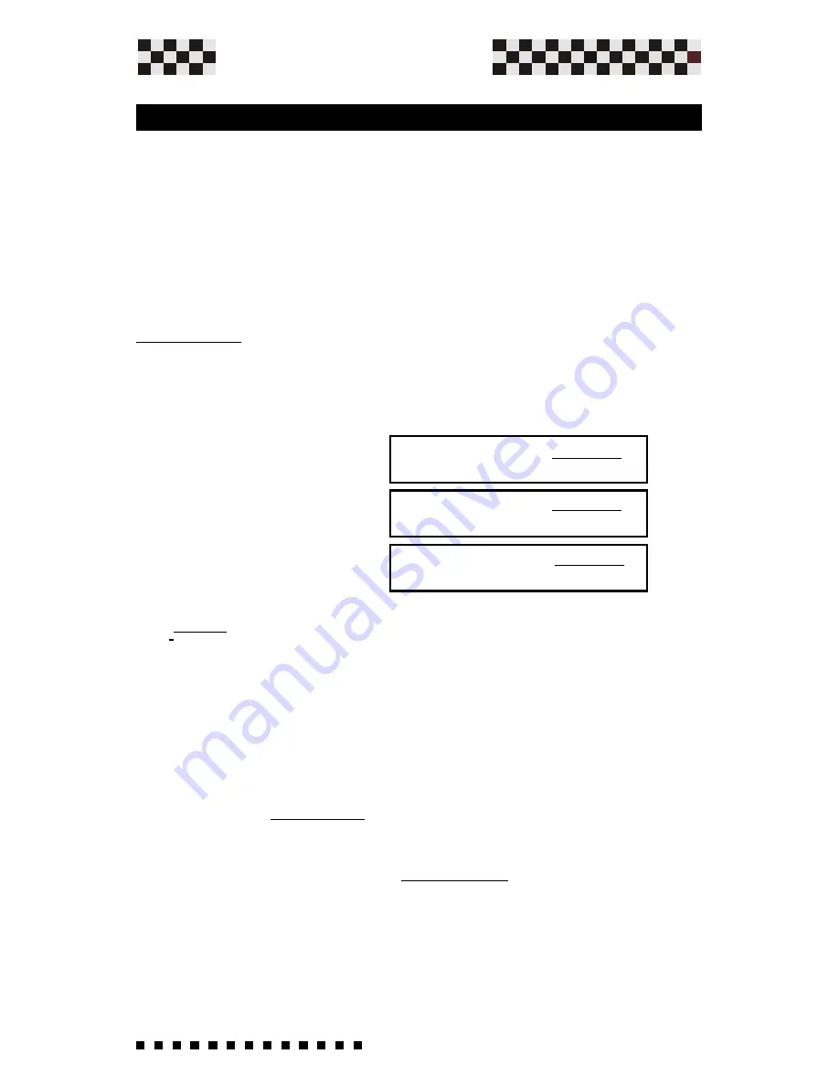
                   RA(k ohm) = 166 x         Vref

                                                 E - 1,4 Vref

                   RA(k ohm) = 159 x         Vref

                                                 E - 3,3 Vref

                   RA(k ohm) = 158 x         Vref

                                                 E - 5 Vref

Adjustments

5.4 Speed adjustment with Armature feedback

Armature feedback mode may be used as speed feedback

when a tachogenerator is not fitted to the motor.

Speed control is then less precise(the regulation range is 1/

20, and below this value the torque is reduced).

This funciton will be enabled by solder bridge 

S7 Closed, S12

open, 

and mounting in the socket 

RA 

and  

RCA

  resistors.

RA resistor

 It will be mounted on the personalization zone to

adapt the system to the voltage motor costant.

To calculate it  use this equation:

RA(kohm) = 166 x       10            = 36 Kohm

                               60 -  1,4 x10

E = 3000 x  20  = 60

1000

WHERE:

E = n x  Ke

       1000

Ke= Servomotor BEMF at 1000 rpm

Vref= Max voltage reference.

n= max speed express in rpm.

Use the nearest commercial value, 33 Kohm.

Example:

Servom

otor  with  

Ke

=20   

n

=3000 RPM  

 Vref

=10 For MCS

Plus 60.

MCS PLUS 60

MCS PLUS 140

MCS PLUS 200

CONTINUE

Summary of Contents for Microspeed Plus 140

Page 1: ...allation procedures are only performed by qualified personnel in accordance with local safety guidelines Whoever installs the equipment must follow all of the technical instructions printed in this ma...

Page 2: ...2 Indicator LEDs and Regulations 2 0 Potentiameter Adjustments 18 19 2 1 Protections 20 2 2 Indicator LEDs 21 3 Installation 3 0 Installation Notes 22 3 1 Ventilation 22 23 3 2 Power Supply Construct...

Page 3: ...7 5 2 Solder Bridges 48 49 5 3 Speed Adjustments with D T Feedback 50 5 4 Speed Adjustments with Armature Feedback 51 52 5 5 Speed Balance Adjustments Offset 52 5 6 Nominal and Peak Current Adjustment...

Page 4: ...emove drive from the power supply net before working on the drive Warning This symbol is present in all particularly important points It s used where the intent is to highlight useful considerations p...

Page 5: ...te it in case of abnormalities therefore the motor becomes uncontrolled this could cause the stoppage or idle motor for a period determined by the type of system used In some cases the drive could res...

Page 6: ...ays to accommodate most applications Three types of velocity feedback are available with these drives Refer to Chapter 5 for the setup procedures that will effect your application Feedback Types Tacho...

Page 7: ...m Tachogenerator Speed Feedback from Armature Speed Feedback from Encoder External Power Supply Brake for plus 60 External Power Supply Brake for plus 140 External Power Supply Brake for plus 200 Stan...

Page 8: ...er and Hall Signal Power Supply V Optional Auxiliary power supply Encoder Max Freq Optional Band Width Weight Microb plus Weight Microb plus w booster Humidity TECHNICAL DATA CHARACTERISTICS Size I no...

Page 9: ...0 poles 5 08 Extractable Phoenix Terminals 6 6 poles 3 81 Phoenix Signal Terminals 7 6 poles 3 81 Extractable Phoenix Terminals 8 Power Terminals AUGAT 9 Product Cover 10 Fixing screws 11 Serial Numbe...

Page 10: ...10 Service Manual Plus MICROSPEED MICROSPEED PLUS KV DER BIL VEL ACC M M AT AT 1 4 Drive Dimensions NOTE Dimensions mm INCHES General Description...

Page 11: ...11 Service Manual Plus MICROSPEED MICROSPEED PLUS WITH BOOSTER KV DER BIL VEL ACC M M AT AT General Description NOTE Dimensions mm INCHES...

Page 12: ...t ORD is AXOR s internal order number which relates to product distribution Always quote this number when asking for technical assistance 1 5 Drive Label Description example General Description Name M...

Page 13: ...13 Service Manual Plus MICROSPEED 1 6 Connections General Description...

Page 14: ...closed Applying a signal between zero and 10V you receive the current limitation output from zero to max drive size Ex Mcs Plus10 20A 5V limits the current to 10A Mcs Plus 14 28A 3 2V limits the curre...

Page 15: ...rrent output In this mode the velocity loop is automatically disabled Continued Drive Common Ground Corisponds to power supply s nega tive AT input Power Supply 10Vdc 4mA Max Power Supply 10Vdc 4mA Ma...

Page 16: ...V to 24Vdc Low logic level 1 5V 5Vdc 250mA Max Solder bridge S13 closed 12Vdc 250mA Max Solder bridge S13 open Encoder input Channel B High logic level from 3 2V to 24Vdc Low logic level 1 5V Logic in...

Page 17: ...ting a positive Voltage between 5Vdc e 24Vdc on said input When the current on said input is absent motor rotation blockage intervenes in a counter clockwise sense See Chapter 3 10 AT Input Positive c...

Page 18: ...r clockwise ccw to reduce the motor speed The range of the adjustment is 20 Note Potentiometer is disabled in torque mode BIL Offset adjustment Adjust this potentiometer to cancel any motor speed when...

Page 19: ...ed Plus the KV and DER functions are constituted by Hexadecimal rotating switch indentified with numbers from 0 to F With 0 you have the minimun function attainable and with F you receive the maximum...

Page 20: ...are Reversible and Irreversible Reversible Protection Intervention The drive is automatically reset restarted when the cause of intervention has been corrected Over Current limitation Over under volta...

Page 21: ...indicator is lit when the drives internal temperature reaches the max value Remove power and wait for the drive to cool before re applying power If operating temperatures are close to the Max operati...

Page 22: ...guarantee efficient cooling by the drive itself The positioning inside the box must satisfy the following dispositions For best results from drive guarantee that inside the electrical box a temperatu...

Page 23: ...lus n a Unavailable size with Microspeed Plus Available with Microspeed Case PM1 N Microspeed Plus with normal radiator See Chapter 1 5 B Microspeed Plus with added radiator Booster See Chapter 1 4 NV...

Page 24: ...e the schematic and formulas provided below to design a supply that will be trouble free and handle the power needed by the drive Transformer A single ground is used in the drive that is connected to...

Page 25: ...m I motor A Ri Winding resistance Ohm Ke Voltage constant V kRPM n MAX speed RPM V1 Dc VMotor 0 9x1 36 Voltage The primary voltage depends on what is available locally for a single phase The secondary...

Page 26: ...phase due to overcurrent from the capacitors max power per trasformer is 7KVA Where Pn Motor nominal power each motor n max speed of motor in RPM Cn nominal torque of motor in Nm Pn Motor n x Cn 9 55...

Page 27: ...energy during the motor s braking phase Where RS is the resistor value in Ohm P is the power of said resistor in Watt Discharge resistor The bleeder resistor is used to drain the charge from the filte...

Page 28: ...nsformer to protect against harm to the system and the transformer itself They need to be of the slow blow type to handle current in rush at power up Locate the primary fuse F1 on the hot leg of the A...

Page 29: ...correct W i r i n g Technique Use This In case of connecting more than one axle to a single supply always connect each drive DIRECTLY to the supply and keep the wires as short as possible twist the an...

Page 30: ...30 Service Manual Plus MICROSPEED 3 4 Ground and Shield Connections Installation...

Page 31: ...turbances in the net The Motor ground cable has to be external not inserted in a multipolar cable with minimun section 1 5 mmq 0 059 square inch Drive power and signal cables must be shielded The cabl...

Page 32: ...ion also to the controller 3 Using the division of cables technique Separate power cables from signal cables 4 The correct ground connection of predisposed parts Of all of the mentioned system the use...

Page 33: ...ommends connecting the filter before the power supply transformer This method besides offering better disturbance soppression result also allows for the use of filters capable of supporting a lot less...

Page 34: ...erential adjustements and nominal current in accordance with operational tem perature Instructions for EMC requirements continued Below is a table showing the electrical characteristics of our recomme...

Page 35: ...re mounted is connected to ground Power and Command Signal condotors should not be placed in the same channels keep separate Avoid twisting crossing etc If crossing is inevitable try to cross at a 90...

Page 36: ...or 4 It is possible to use an external power supply for this function 24Vdc Remember to also connect the GND of the power supply to Connector 3 3 6 Examples of Microspeed Plus Connections On connector...

Page 37: ...cation with speed reference connections using an internal MICROSPEED PLUS power supply The speed potentiometer must have an included value between 10 and 47Kohm The following diagram shows an applicat...

Page 38: ...s closed S9 and S12 is open The formula to determine the value of Ving to apply in TPRC in order to obtain requested current is the following Other examples Mcs Plus10 20A 5V gives current of 10A 5V g...

Page 39: ...m zero to max size drive s For this configuration the soldering point S8 is open S9 closed The speed ring remains active and uses the input reference signal Example Mcs Plus 10 20A 5V limits the curre...

Page 40: ...ect a resistence of 1 4W 1 8W between the TPRC terminal and the GND terminal or a potentiometer connected as in figure 5 With external Resistance of 47K you limit the current at 50 of I Max of size Ex...

Page 41: ...rds to this input always has priority To enable such a function you must Open soldering point S10 Open soldering point S12 disable a internal allarm for missing tachogenerator or encoder Then connect...

Page 42: ...quare mm up to 10 20 The M and M drive outputs can be connected directly to the motor terminals The minimum motor inductance value is 0 5 mH In the case of motors driven with armature inductance lower...

Page 43: ...IP resitors are not mounted Ex Microspeed Plus 140 10 20A 20A peak for 2 seconds 10A upon return Encoder speed adjustment for 3000 rpm at 10V ref with encoder of 1000 Imp rev RDT resistor 22Kohm KV an...

Page 44: ...application norm to always supply the Enable command after the powering up the drive Furnish the reference signal Increase the speed reference signal up to minimum value approx 1V and observe the moto...

Page 45: ...servomotor follow these procedures If changes need to made to the internal drive setting powering please wait at least 10 seconds after the power has been removed and the OK LED is off All of the per...

Page 46: ...lder bridge S6 and insert R GAIN if a change is required Consult factory for the correct value Resistor value that form the proportional integral network of the velocity Loop gain Standard values are...

Page 47: ...t capacitor increases the velocity loop derivative constant Capacitor value that form the proportional integral network of the velocity Loop gain Standard values is 47nF there are disabled by opening...

Page 48: ...F Consult factory for proper use S6 Normally closed If Open you must insert theNew GAIN resistor Static Gain Standard value 22ohm S7 Normally open If closed enables Armature Feedback See chapter 5 4 5...

Page 49: ...chogenerator or Encoder S13 Normally closed Power supply on terminal Vs 5Vdc If open configure V 12Vdc Only for Optional Encoder S14 S15 Normally open If closed you insert for each encoder input a pul...

Page 50: ...lue of the resistor To calculate it please use the following equation Example KDT 10 n 3000 Vref 10 Where Rdt is the value expressed in Kohm with a power rating of 1 8 or 1 4w Kdt is the tachogenerato...

Page 51: ...s reduced This funciton will be enabled by solder bridge S7 Closed S12 open and mounting in the socket RA and RCA resistors RA resistor It will be mounted on the personalization zone to adapt the syst...

Page 52: ...er commercial value avalaible WHERE n max speed expressed in rpm Ri Total motor resistance with brushes Ipk Peak current size of the drive Ke Sevomotor BEMF at 1000 rpm Vref Max voltage reference Adju...

Page 53: ...8 6 7 4 3 3 2 2 5 1 1 2 1 S C M 1 6 9 0 2 9 0 6 8 0 8 7 0 1 7 0 3 6 0 5 5 0 6 4 0 9 3 0 2 3 0 5 5 2 S C M 5 1 4 2 3 2 1 2 9 1 7 1 5 1 3 1 2 1 1 8 0 2 1 6 S C M 6 8 5 5 5 2 5 7 4 3 4 8 3 3 3 7 2 3 2 2...

Page 54: ...his function is enabled by solder bridges S2 S4 closed It allows adjustment of the ramp slope during both acceleration and deceleration Adjusting the ACC potentiomenter located in front of the drive c...

Page 55: ...ted to the motor Connect a square wave 0 5 hz 1V function generator to the input speed reference terminals Connect the channel A probe of the memory oscilloscope to the test point TEST1 The ground of...

Page 56: ...ust clockwise cw using Der potentiometer until achieving a situation as shown on the left Caution Do not set KV too high it can cause unnecessary motor heating caused from ocsillating currents in the...

Page 57: ...red O C LED comes on Short circuit between motor terminals or motor winding is connected to ground Switch off and measure with tester 4 During motor deceleration phase the green OK LED blinks You ve e...

Page 58: ...If the encoder s absorption is unknown please check it by a milliamperometer connected in series to Vs If the value is higher please use an external power supply Encoder inputs Push Pull Line driver...

Page 59: ...59 Service Manual Plus MICROSPEED Encoder Connections Options The following diagram shows typical connections between the drive and a brushed motor The Encoder power comes from the V connector 11...

Page 60: ...tion Encoder Connection from External Power Supply The figure below shows a self powered MICROSPEED PLUS with the Encoder signalS are powered externally The Ground of the external power supply must be...

Page 61: ...the motor will be and find out what the line count PPR of the encoder is before using the formula This is a two part for mula the first part gives a factor based on rate the second part determines th...

Page 62: ...figure Such logic signals must be furnished to the Microspeed Plus by a controller which must be able to elaborate the motor s speed ring and possibly the positioning ring The signals high logic leve...

Page 63: ...th the motor For additional information contact AXOR Signal Connector Description 1 Drive OK Open Collector output 50mA Max Normally closed opens when in protection mode 3 and12 GND Common zero signal...

Page 64: ...ic Compatibility Directive 89 336 92 31 93 68 And that the following technical standards were applied CEI EN 60204 1 Safety of machinery Electrical equipment of machines Part 1 General requirements CE...

Reviews: