5
Assembly
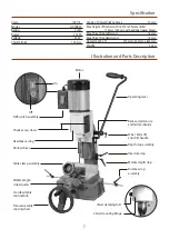
Please take some time to read the section entitled
“Illustration and Parts Description” to identify the
various parts of your machine so that you are familiar
with the terminology we will use to enable you to set
up and operate your Morticer safely and correctly.
Place the machine onto a suitable surface, at a height that
will enable you to work comfortably and to ensure that
there is adequate room on either side for the size of timber
you plan to use. Once you are happy bolt the morticer
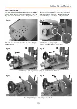
down. Loosen the locking caphead screw (a) to raise the
morticers head assembly. Locate the operating lever (A)
and the M6 x 16mm lift and shift handle (E), introduce the
operating lever through the rack and pinion assembly,
then secure the lever in place using the M6 lift and shift
handle (E) (See fig 2).
Locate the operating wheel Shaft (C), remove the phillips
screw, clamping washer and M6 x 23mm caphead screw
and place them safely aside (See figs 3 and 5). Slide
the machined cutout onto the transverse table shaft
mechanism, line up the pre-drilled hole with the one in the
table shaft mechanism and secure them in position using
a 5mm allen key and the M6 x 23mm caphead screw you
removed earlier (See figs 4 and 5).
Rack and pinion assembly
Remove the phillips screw
and clamping washer.
Secure the wheel shaft (C) to the table
shaft using the M6 caphead screw.
Slide the operating wheel (B)
onto the operating shaft (C).
Locating
key
Slot
Slide the machined cutout onto the
transverse table shaft mechanism.
Table shaft
mechanism
Fig 1.
Fig 3.
Fig 2.
Fig 4.
Fig 6.
A
C
C
B
E
a
Fig 5.
M6 Caphead
screw


