6
Assembly
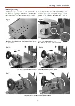
Locate the operating wheel (B), slide it on to the operating
wheel shaft (C) as shown in fig 6 (Note: Make sure the
locating key engages into the shafts machined slot).
Secure using the phillips screw and clamping washer you
removed earlier (See fig 7).
Move the table to the left by turning the operating wheel
(B), thus reveling the grub screw beneath. Locate one of
the two distance stop rods (D) and a ring collar clamp (F),
slide the ring collar clamp (F) onto the distance stop rod
(D) and lightly tighten by turning the lift and shift handle,
see fig 8 on the previous page. Line up the countersink
mark on the rod (D) with the grub screw, (make sure the
grub screw is raised fully) slide the rod (D) into the pre-
drilled hole to the end of casting and tighten the grub
screw (See figs 9,10 and 11) repeat for the opposite side.
Remove locking caphead screw (a) (see page 5), that locks
the morticers head assembly and replace it with the M6 x
30mm lift and shift handle (E) (See fig 12).
Secure the operating wheel (B) using the phillips screw
and clamping screw.
Slide the ring collar clamp (F) onto the distance stop rod
(D) and lightly tighten.
Countersink mark
Grub screw
Fig 7.
Fig 9.
Fig 11.
Fig 8.
Fig 10.
C
F
E
Fig 12.


