Set Up and Adjustment
20
3
2
4
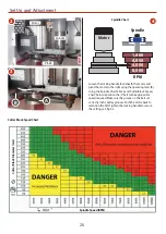
Loosen the locking handle (A) beneath the motor and
pivot the motor to the right using the operating lever (B).
Using the ‘Spindle Chart’ above and ‘Cutter Block Speed
Chart’ below reposition the ‘V’ belt to the appropriate
speed required. Make sure the grooves in the belt set
correctly in the pulley grooves. Push the motor back to
retention the belt. Tighten the locking handle to secure
the setting, see fig 3-4.
A
B
Spindle
Motor
‘V’ Belt
Cutter Block Speed Chart
Spindle Chart
Cutt
er Blo
ck D
iamet
er (mm)
Spindle Speed (RPM)
1,400
RPM
Spindle
4,000
6,000
8,000
Motor


