MANO882 Series Mini ITX Board
Board and Pin Assignments
9
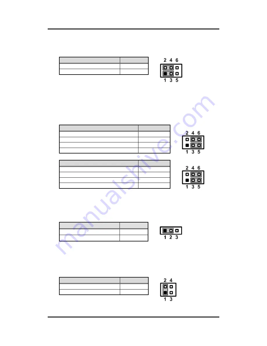
2.3.1
Audio Output Selection (JP1)
Use this jumper to select line-out or speaker-out as source of audio output on audio
connector. When speaker-out is used, it delivers 1W/channel continuous at
8Ω loads.
2.3.2
COM2 and COM1 Data/Power Selection (JP2 and JP3)
The COM2/COM1 port has +5V level power capability on DCD and +12V level on RI by
setting jumper JP2/JP3. When this port is set to +5V or +12V level, please make sure its
communication mode is RS-232. You can change the communication mode
(RS-232/422/485) via BIOS setting, see section 5.4.
JP2
JP3
2.3.3
Restore BIOS Optimal Defaults (JP5)
Put jumper clip to pin 2-3 for a few seconds then move it back to pin 1-2. Doing this
procedure can restore BIOS optimal defaults.
2.3.4
LVDS Brightness Control Mode Setting (JP6)
This jumper enables you to select PWM or voltage control mode for inverter connector
(CN18). These two control modes are for adjusting the brightness of LVDS panel.
Function
Setting
Line-out (Default)
1-3, 2-4 close
Speaker-out (w/ amplifier)
3-5, 4-6 close
Function
JP2 Setting
Power: Set CN3B pin 1 to +5V level
1-3 close
Data: Set CN3B pin 1 to DCD (Default)
3-5 close
Power: Set CN3B pin 9 to +12V level
2-4 close
Data: Set CN3B pin 9 to RI (Default)
4-6 close
Function
JP3 Setting
Power: Set CN3A pin 1 to +5V level
1-3 close
Data: Set CN3A pin 1 to DCD (Default)
3-5 close
Power: Set CN3A pin 9 to +12V level
2-4 close
Data: Set CN3A pin 9 to RI (Default)
4-6 close
Function
Setting
Normal operation (Default)
1-2 close
Restore BIOS optimal defaults
2-3 close
Function
Setting
PWM mode (Default)
1-2 close
Voltage mode
3-4 close
Summary of Contents for MANO882 series
Page 6: ...vi iAMT Settings 83 iAMT Web Console 86 ...
Page 10: ...MANO882 Series Mini ITX Board 4 Introduction This page is intentionally left blank ...
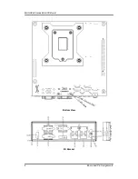
Page 12: ...MANO882 Series Mini ITX Board 6 Board and Pin Assignments Bottom View I O Bracket ...
Page 38: ...MANO882 Series Mini ITX Board 32 Hardware Installation This page is intentionally left blank ...
Page 41: ...MANO882 Series Mini ITX Board Hardware Description 35 ...
Page 43: ...MANO882 Series Mini ITX Board Hardware Description 37 ...
Page 44: ...MANO882 Series Mini ITX Board 38 Hardware Description ...
Page 46: ...MANO882 Series Mini ITX Board 40 Hardware Description This page is intentionally left blank ...
Page 74: ...MANO882 Series Mini ITX Board 68 AMI BIOS Setup Utility This page is intentionally left blank ...

