background image

22


AutoView 2000 Installer/User Guide

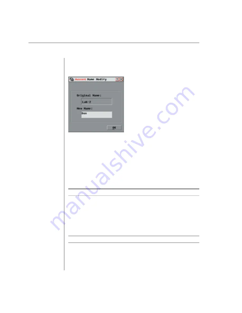
To assign names to servers:

1. 

In the Names dialog box, select a server name or port number and click 
Modify. The Name Modify dialog box appears.

Figure 3.4: Name Modify Dialog Box

2.  Type a name in the New Name box. Names of servers may be up to 15 

characters long. Legal characters include: A-Z, a-z, Ø-9, space and hyphen.

3. Click 

OK to transfer the new name to the Names dialog box. Your selection 

is not saved until you click OK in the Names dialog box. 

4.  Repeat steps 1-3 for each server in the system.

5.   Click OK in the Names dialog box to save your changes.

-or-
Click or press 

Escape 

to exit the dialog box without saving changes.

NOTE: If an AVRIQ has not been assigned a name, the EID is used as the default name.

Assigning device types

While the appliance automatically discovers cascade KVM switches attached to 

your unit, you will need to specify the number of ports on the cascade switch 

through the Devices dialog box. You will see an Sw-8 or Sw-24 appear in the 

Type category for the cascade switch. Select the switch from the list and the 

Modify button appears, allowing you to assign it the appropriate number of ports.

NOTE: The Modify button will only be available if a confi gurable switch is selected.

To access the Devices dialog box:

1. 

Press 

Print Screen

. The Main dialog box will appear.

2. Click 

Setup - Devices. The Devices dialog box appears.

Summary of Contents for AutoView 2000

Page 1: ...Installer User Guide AutoView 2000...

Page 2: ...lated dangerous voltage within the product s enclosure that may be of sufficient magnitude to constitute a risk of electric shock to persons POWER OFF This symbol indicates the principal on off switch...

Page 3: ...ks of Avocent Corporation AutoView is a registered trademark of Cybex Computer Products Corporation OSCAR is a registered trademark of Apex Inc Energy Star is a registered trademark of the Environment...

Page 4: ...ion of this equipment in a residential area is likely to cause harmful interference in which case the user will be required to correct the interference at his own expense Canadian Notification This di...

Page 5: ...our AutoView System 13 Chapter 3 Basic Operations Controlling Your System at the Analog Ports 17 Viewing and Selecting Ports and Servers 17 Navigating OSCAR 19 Configuring OSCAR 20 Displaying Version...

Page 6: ......

Page 7: ...Contents Features and Benefits 3 Safety Precautions 5 1 Product Overview...

Page 8: ......

Page 9: ...retaining unique server names and Electronic ID EID numbers for each attached server The AVRIQ is powered directly from the server and provides Keep Alive functionality even if the AutoView is not pow...

Page 10: ...olution for analog VGA SVGA and XGA video Achieve resolutions of up to 1600 x 1200 with a 10 foot cable and up to 800 x 600 with a 50 foot cable Resolutions will vary depending upon the length of cabl...

Page 11: ...esulting from user supplied cable To avoid potentially fatal shock hazard and possible damage to equipment please observe the following precautions Do not use a 2 wire extension cord in any Avocent pr...

Page 12: ...not compromised Mechanical Loading Mounting of the equipment in the rack should be such that a hazardous condition is not achieved due to uneven mechanical loading Circuit Overloading Consideration sh...

Page 13: ...Contents Getting Started 9 Rack Mounting Your AutoView 9 Installing the AutoView 2000 10 Setting Up Your AutoView System 13 2 Installation...

Page 14: ......

Page 15: ...n Guide Additional items needed One AVRIQ module and UTP cabling per attached server or switch Optional Rack mounting kit Rack Mounting Your AutoView NOTE Rack mounting kits are sold separately Your A...

Page 16: ...ts are not included with the rack mount kit 5 Mount the switch assembly to the rack cabinet by matching the holes in the short side of each bracket to an appropriate set of matching holes on your rack...

Page 17: ...ou will be connecting to the unit 3 Attach one end of the CAT 5 cabling that will run between your AVRIQ and AutoView unit to the RJ45 connector on the AVRIQ module 4 Connect the other end of the CAT...

Page 18: ...ion In a cascaded system each ARI port will accommodate up to 24 servers See the following table for legacy switches compatible with the AutoView 2000 system Legacy Switch Support Legacy Product Model...

Page 19: ...g to the instructions included with the device 6 Power cycle the cascade switch to enable the cascade code 7 Repeat steps 2 5 for all cascade switches you wish to attach to your system To connect loca...

Page 20: ...14 AutoView 2000 Installer User Guide...

Page 21: ...the Analog Ports 17 Viewing and Selecting Ports and Servers 17 Navigating OSCAR 19 Configuring OSCAR 20 Displaying Version Information 28 Scanning Your System 30 Broadcasting to Servers 32 Changing Yo...

Page 22: ......

Page 23: ...n OSCAR generated port list by default when you first launch OSCAR The Port column indicates the ARI port to which a server is connected If you connect a legacy KVM switch to the appliance the port nu...

Page 24: ...tton is depressed type the port number and press Enter or If the display order of your server list is by name or EID number Name or EID button is depressed type the first few characters of the name of...

Page 25: ...Does This Print Screen Opens OSCAR Press Print Screen twice to send the Print Screen keystroke to the currently selected device F1 Opens the Help screen for the current dialog box Escape Closes the c...

Page 26: ...CAR You can configure your AutoView 2000 from the Setup menu within OSCAR Select the Names button when initially setting up your appliance to identify servers by unique names Select the other setup fe...

Page 27: ...the AVRIQ so even if you move the cable server to another ARI port the name and configuration will be recognized by the appliance NOTE If a server is turned off its respective AVRIQ will not appear i...

Page 28: ...r Click X or press Escape to exit the dialog box without saving changes NOTE If an AVRIQ has not been assigned a name the EID is used as the default name Assigning device types While the appliance aut...

Page 29: ...numbered sequentially 06 01 06 02 and so on To assign a device type 1 In the Devices dialog box select the desired port number 2 Click Modify The Device Modify dialog box appears Figure 3 6 Device Mo...

Page 30: ...order of servers 1 Select Name to display servers alphabetically by name or Select EID to display servers numerically by EID number or Select Port to display servers numerically by port number 2 Click...

Page 31: ...creen The Main dialog box will appear 2 Click Setup Flag The Flag dialog box appears Figure 3 8 Flag Dialog Box To determine how the status flag is displayed 1 Select Name or EID to determine what inf...

Page 32: ...e mouse You will then need to type in your password to continue Use the Security dialog box to lock your console with password protection set or change your password and enable the screen saver NOTE I...

Page 33: ...result from the use of Energy mode with monitors not compliant with ENERGY STAR 5 Optional Click Test to activate the screen saver test which lasts 10 seconds then returns you to the Security dialog...

Page 34: ...disconnects the user from a server no server is selected The status flag displays Free To exit the screen saver mode Press any key or move your mouse The Main dialog box appears and any previous serv...

Page 35: ...tion The AVRIQ Selection dialog box appears Figure 3 12 AVRIQ Selection Dialog Box 4 Select an AVRIQ to view and click the Version button The AVRIQ Version dialog box appears For more information on l...

Page 36: ...e no servers in the scan list your cursor will appear in a blank line at the top of the list or To add a server to the end of the list place your cursor in the last server entry and press the Down Arr...

Page 37: ...removed 2 Press Delete or Press Shift Delete to remove the selected server and all entries below it 3 Click OK To start the scan mode 1 Press Print Screen The Main dialog box will appear 2 Click Comm...

Page 38: ...roadcast The Broadcast dialog box appears Figure 3 16 Broadcast Dialog Box NOTE Broadcasting Keystrokes The keyboard state must be identical for all servers receiving a broadcast to interpret keystrok...

Page 39: ...dialog box appears 4 Click the Broadcast Enable checkbox to activate broadcasting The Broadcast Enable Confirm Deny dialog box appears Figure 3 17 Broadcast Enable Confirm Deny Dialog Box 5 Click OK t...

Page 40: ...hecked users may share access to a single server Only one may be in control at any given time To access the Switch dialog box 1 Press Print Screen The Main dialog box will appear 2 Click Setup Switch...

Page 41: ...Contents Appendix A FLASH Upgrades 37 Appendix B Technical Specifications 41 Appendix C Technical Support 42 Appendices...

Page 42: ......

Page 43: ...e you have saved the firmware update and unzip the file 3 Double click to run the file WUpDateAvct exe 4 In the dialog box that displays select the desired language and COM port 5 Click Load 6 Once th...

Page 44: ...1 Press Print Screen The Main dialog box will appear 2 Click Commands AVRIQ Status The AVRIQ Status dialog box appears Figure A 1 AVRIQ Status Dialog Box 3 Click one or more types of modules to upgra...

Page 45: ...sions The Version dialog box appears Figure A 3 Version Dialog Box 3 Click AVRIQ to view individual cable version information The AVRIQ Selection dialog box appears Figure A 4 AVRIQ Selection Dialog B...

Page 46: ...Dialog Box 6 Click OK to initiate the upgrade and return to the Status dialog box NOTE During an upgrade the AVRIQ status indicator in the Main dialog box will be yellow The AVRIQ is unavailable whil...

Page 47: ...ght 3 6 kg 8 lb without cables Heat Dissipation 92 BTU Hr Airflow 8 cfm Power Consumption 12 5 W AC input power 40 W maximum AC input voltage rating 100 to 240 VAC Autosensing AC input current rating...

Page 48: ...w for the fastest possible service 1 Check the pertinent section of this manual to see if the issue can be resolved by following the procedures outlined 2 Check our web site at www avocent com support...

Page 49: ...Appendices 43...

Page 50: ...44 AutoView 2000 Installer User Guide...

Page 51: ...e is individually tested under load 2 If defect or malfunction was caused by abuse mishandling unauthorized repair or use other than intended 3 If unauthorized modifications were made to product 4 If...

Page 52: ...353 61 715 292 Fax 353 61 471 871 Avocent Asia Pacific Singapore Branch Office 100 Tras Street 15 01 Amara Corporate Tower Singapore 079027 Tel 656 227 3773 Fax 656 223 9155 Avocent Germany Gottlieb D...

Reviews: