background image

Connection 


Matrix 


Co m p uter 

DVR


2.6 Connect the keyboard in the system 

The user can use the keyboard to control the alarm 

box, and to connect the dome via the alarm box. Please 

see the alarm box user manual for more details regarding 

the connections. Every alarm box only can connect to 

one dome camera. 

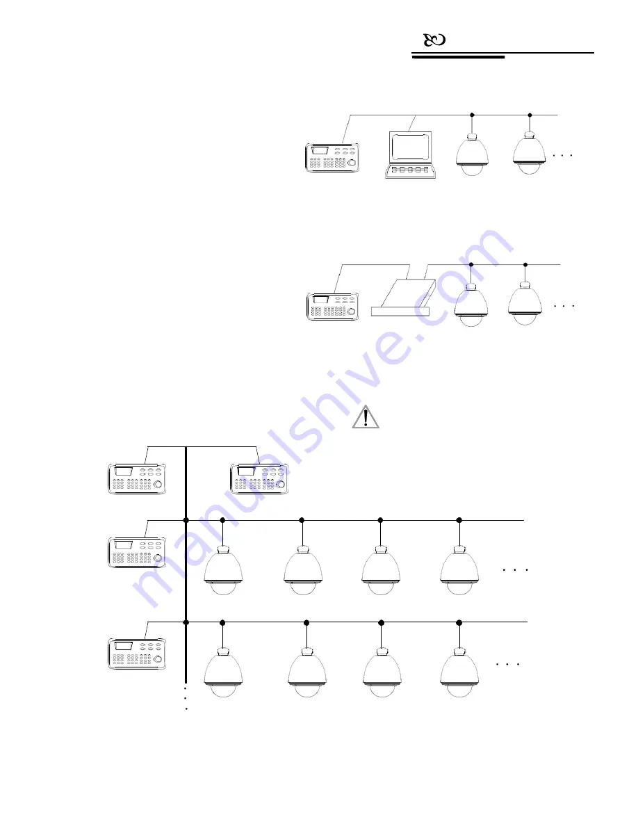
The  keyboard  can  control  the  matrix,  and  control 

the  domes  indirectly  by  the  matrix  (see  Picture2-6.1). 
When  the  keyboard  is  not  connected  to  the  matrix,  it 
connects  to  a  computer  (DVR),  and  controls  the  dome 
(see  Picture2-6.2);  or  the  keyboard  can  also  control  the 
dome directly without DVR. 


Several keyboards and dome cameras can be 

connected in parallel, and access RS485 bus line. Each 

keyboard can control a dome independently. Working in 

this mode requires the user to set a main keyboard (the 

main keyboard ID is set to 1), and the Baud rate of the 

keyboard is set to 9600bps (see Picture 2-6.3). 


Keyboard 


Do m e 1 

Do m e 2 


Picture 2-6.2 


In  the  previous  pictures,  the  connections  between 

keyboard  and  keyboard  or  between  keyboard  and 

computer  are  all  via  RS232,  however,  when  the  distance 

between  devices  is  more  than  20m,  it  is  suggested  that 

RS485 should be used. 

Keyboard 

Dome 1 

Dome2  


Picture 2-6.1 


1.


Using one RS485 cable enables the user to 

control up to 32 pieces of equipment. With 

that being said, a keyboard can directly control 

up to 31 domes. 

NOTICE 

2.


The system may have up to 4 keyboards 

simultaneously, and each keyboard holds a 

different ID. 


Keyboard1 

Keyboard2 


Keyboard3 


Dome1 

Dome2 

Dome3 

Dome4 


keyboard4 


Dome5 

Dome6 

Dome7 

Dome8 


Picture 2-6.3 

Summary of Contents for AV-3106

Page 1: ...Model AV 3106 Keyboard Controller User Manual V3 01 English Please read this User Manual throughout before using www avipas com...

Page 2: ...1 Current carrying capacity 6 3 2 LCD 6 3 3 Use joystick to control dome 6 3 4 Change object dome 7 3 5 Lens control 7 3 6 Set dome functions 7 3 6 1 Preset 7 3 6 2 Scan 7 3 6 3 Pattern 8 3 6 4 Tour 8...

Page 3: ...ally 14 4 3 4 Resume factory default settings 14 4 4 Protocol settings 14 4 4 1 Pelco matrix model 14 4 4 2 Direct control model 14 4 4 3 DVR control model 15 4 5 Display the keyboard information 15 4...

Page 4: ......

Page 5: ...se to any exothermic object for a long time 1 2 Functions and Characteristics Using a RS485 bus line this keyboard can connect up to 31 domes in the direct control mode This keyboard is compatible wit...

Page 6: ...12V DC AC power The keyboard itself is equipped with an adaptor which converts 230VAV to 9VDC 2 1 3 EIA RS232 interface EIA RS232 interface is used to expand the functions to control the menu handler...

Page 7: ...distance is 1200m 2 3 1 RJ45 local connection 2 3 2 RS422 remote connection Connect one end of RS422 cable to RS422 interface on the back plate of CM6700 REMOTE KEYBOARD s and connect the other end t...

Page 8: ...B can be found following the instructions Dome cameras from different manufacturers may acquire different connections Please see to the dome installation manual before connecting to the keyboard 2 5 C...

Page 9: ...s line Each keyboard can control a dome independently Working in this mode requires the user to set a main keyboard the main keyboard ID is set to 1 and the Baud rate of the keyboard is set to 9600bps...

Page 10: ...y on the LCD 3 2 LCD LCD is used to display the basic information of the keyboard including the keyboard model keyboard ID object camera object monitor ID baud rate etc In the last line there are keyb...

Page 11: ...Wide to get a lower magnification Let go to stop Magnification can also be controlled by rotating the joystick Focus control Press Far to manually move the focus farther away from the object Let go t...

Page 12: ...Pattern the corresponding pattern will run 3 6 4 Tour Run tour N Tour Tour Press tour number then press Tour run tour If system has only one tour path then press only Tour to run the tour directly If...

Page 13: ...s it ll jump over 16 domes in a forward order Stop stop the switch process 3 8 2 Call the main menu of matrix Shift Set call the main menu The menu will display on the object monitor Please refer to t...

Page 14: ...keyboard ID is set successfully Return to the previous menu Press Prev or move the joystick to the left Picture 4 1 1 4 it ll return to the previous menu 4 1 Keyboard ID settings 4 1 1 Set keyboard ID...

Page 15: ...l show as below see Picture 4 1 3 1 Input the old password 892226 then press Enter and the cursor will jump to the second row Input the new password press Enter the cursor will jump to the third row I...

Page 16: ...o 1 or the keyboard won t work Picture 4 2 1 1 Press 1 again to set the preset positions By operating joystick locate the best position and adjust the lens then press 1 to save this preset position Se...

Page 17: ...o input a pattern number 1 4 Press 2 to set the pattern path move the camera and adjust the lens to capture the ideal image The dome camera will record pause time lens settings and a series of actions...

Page 18: ......

Page 19: ...up is complete Picture 4 3 4 3 will show again Press Prev to go back to the previous menu 4 3 1 Set the alarm input channel and the alarm spot 1 Enter the main menu The LCD screen will show as below s...

Page 20: ...Alarm box setup menu and the LCD screen will show as Picture4 3 1 2 Press 4 to resume factory default settings and the LCD screen will show as below see Picture 4 3 3 2 Picture 4 4 1 1 4 4 2 Direct c...

Page 21: ...on the keyboard to easily switch between the DVR control mode and the keyboard direct control mode After switching to the keyboard direct control mode the protocol used for keyboard and dome camera w...

Page 22: ...configuration is not in conformity with the RS485 standards so problems such as signal reflections poor anti interference performance will arise when the devices are relatively far away from each othe...

Page 23: ...the scan area 1 Scan High speed dome Input 1 then press Scan to run the scan Set N Pattern High speed dome Press Set and input the pattern number then press Pattern to record pattern path Set 0 Patte...

Page 24: ...Appendix 6 Keyboard Menu Index...

Page 25: ...any does offer repair services to out of warranty products Please notice that service fees will be charged For the defected products if it s still under warranty please fill out the warranty form with...

Page 26: ...ion of the company Product specifications and information which were referred to in this document are for reference only We may alter the content at any time and without prior notice Contact Details S...

Page 27: ...ion V3 01 Manufacturer Distributed by AViPAS Inc SWIT Electronics USA LLC www avipas com www swit us 4300 Stevens Creek Blvd Suite 230 3350 Scott Blvd 61 02 San Jose CA 95129 Santa Clara CA 95054 408...

Reviews: