


MLN-192 Option Card Installation
10
6
Lift the tab on the retaining clip and press the card firmly into
the PCIe port and clip.
7
When the card is properly seated in the slot, tighten the exte-
rior captive thumbscrew to secure the faceplate of the card to
the back panel of the E6L.
8
Tighten the rear bracket captive thumbscrew to secure the
back of the card to the back bracket.
9
Re-connect the red and black power cable to the Master
AVB-192 card.
10
Re-connect the Ethernet cable from the E6L to the right-most
port on the Master AVB-192 card.
To re-install a second AVB-192 Network card:
1
Inside the unit, place the face of the card into position in the
slot, with the back of the card tilting upwards.
2
Using two hands, hold the front of the card in place in the slot
with one hand, and slowly move the back of the card down-
wards along the sheet metal until the card is horizontal.
3
Once the card is horizontal, make sure the tab on the faceplate
of the Network card is positioned on the outside of the slot.
4
Align the PCIe connector on the card with the corresponding
PCIe port, and align the flange on the card with the retaining
clip on the PC board.
Figure 40. Inserting the AVB-192 card into its PCIe port
Figure 41. Securing the AVB-192 card to the back bracket
Tightening the rear bracket captive thumbscrew can make it
difficult to re-install other cards above it. If this occurs, leave
these rear bracket captive thumbscrews unattached until all
cards are re-installed, then tighten them to secure each card
to the back bracket.
Figure 42. Re-connecting the Master AVB-192 power cable
Original factory cabling may vary. Follow the instructions
in this guide to achieve the recommended cabling scheme.
Cable colors shown might not match the cables in your E6L.
Figure 43. Placing the card into position inside the engine
Figure 44. Proper position of the Network card faceplate tab
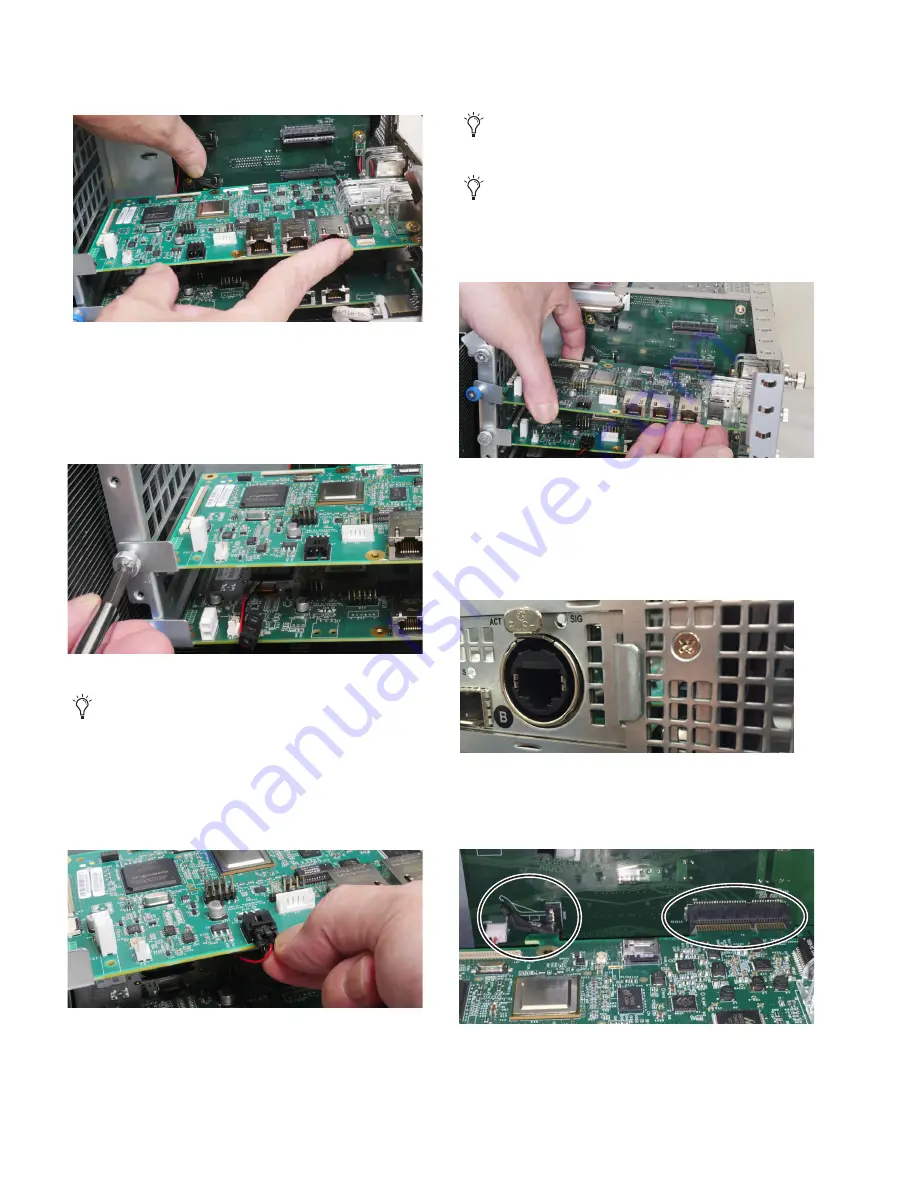
Figure 45. Aligning the and the PCIe connector to the port (right) and
the card flange to the retaining clip (left)


