background image

38

EZ-TOUCH-M Revision 4

4  INSTALLATION

Modicon Modbus Plus Option Card

The EZTouch Panel Models EZ-T10C-FSM, and EZ-T15C-FSM have the Modbus
Plus Option Card installed.  A special connector is attached to these option
boards and is accessible from the bottom of the unit.

The bottom of the plastic back cover has a section that has been removed to
allow access to the Modbus connector (9-pin Female D-SUB) that extends over
the edge of the board. Two types of connectors are available from Modicon for
connecting devices to the network. Each inline drop requires a line connector,
Modicon part number AS-MBKT-085. This part number contains one connec-
tor. The drops at the two ends of the cable, each require a terminating connec-
tor, Modicon part number AS-MBKT-185. This contains two connectors.

The Modbus Plus node address can be set using the first six positions of the
DIP switches located at the top of the option board as shown in the diagram
below. When the board is seated in the panel, setting the DIP Switch in the UP
position is the ON position. There are three Status LEDs on the Modbus Plus
option card:  MBP, TXD, and RXD.  The TXD and RXD LEDs indicate the board
is transmitting or receiving data. The MPB LED (leftmost LED) indicates Modbus
Plus status.

Artisan Technology Group - Quality Instrumentation ... Guaranteed | (888) 88-SOURCE | www.artisantg.com

Summary of Contents for EZTouch EZ-S6M-FSH

Page 1: ...l service in house repair center WE BUY USED EQUIPMENT Sell your excess underutilized and idle used equipment We also offer credit for buy backs and trade ins www artisantg com WeBuyEquipment REMOTE INSPECTION Remotely inspect equipment before purchasing with our interactive website at www instraview com LOOKING FOR MORE INFORMATION Visit us on the web at www artisantg com for more information on ...

Page 2: ...EZTouch Panel Hardware User Manual Revision 4 Manual Part Number EZ TOUCH M Artisan Technology Group Quality Instrumentation Guaranteed 888 88 SOURCE www artisantg com ...

Page 3: ...ge the unit beyond repair Trademarks This publication may contain references to products produced and or offered by other companies The product and company names may be trademarked and are the sole property of their respective owners AVG disclaims any proprietary interest in the marks and names of others Copyright 2000 2003 Autotech Technologies L P All Rights Reserved No part of this manual shall...

Page 4: ...ing Cable Part Number 10 3 SPECIFICATIONS 11 All 6 inch Models 11 8 inch and 10 inch Standard Bezel Models 12 8 inch 10 inch and 15 inch Slim Bezel Models 13 4 INSTALLATION 15 Mounting 16 Method 1 Stud Mounting 16 EZ S6M R EZ S6M F EZ S6M FH EZ S6K EZ S6C F EZ S6C FH Dimensions Cutout 17 EZ S6M RS EZ S6M FS EZ S6M FSH EZ S6C KS EZ S6C FS EZ S6C FSH Dimensions Cutout 18 EZ S8C F and EZ S8C FH Dimen...

Page 5: ...ng 35 Generic DeviceNet I O Option Card 36 Generic Ethernet IP Option Card 37 Modicon Modbus Plus Option Card 38 Generic Profibus DP Option Card 39 Communications Setup 41 Clock 41 COM1 42 Contrast 43 Touchpad Test 43 Display Test 44 Exit 44 Reboot 44 5 MAINTENANCE 45 Shutting Off Power to EZTouch Panel 45 Lithium Battery Replacement 47 Gasket Replacement 48 Panel Status Indicator Light 48 RAM Upg...

Page 6: ... 2 A 5 General Electric 90 30 and 90 70 15 pin D SUB RS 422A P N EZ 90 30 CBL A 6 Mitsubishi FX Series 25 pin RS 422A P N EZ MITSU CBL A 6 Mitsubishi FX Series 8 pin MINI DIN RS 422A P N EZ MITSU CBL 1 A 7 Modicon Modbus RS 232 A 7 Wiring Diagram for the 984 CPU Quantum 113 CPU A 7 Wiring Diagram for AEG Modicon MICRO Series 110 CPU 311 xx 110 CPU 411 xx 110 CPU 512 xx 110 CPU 612 xx A 8 Modicon M...

Page 7: ...iv This page intentionally left blank Artisan Technology Group Quality Instrumentation Guaranteed 888 88 SOURCE www artisantg com ...

Page 8: ... added Siemens PLC Cable added EZTouch Panel RS 422A wiring connections added Mounting options for 8 and 10 inch models changed Revision 2 9 2002 Pages i iv 2 3 5 6 8 13 15 16 18 20 21 23 25 28 31 37 40 46 Index 8 10 and 15 inch Slim Bezel Models added Touchscreen chemical compatibility table added for Slim Bezel models Revision 3 02 2003 Pages i vi 1 2 6 8 10 13 15 23 26 29 30 32 39 43 A 8 A10 A ...

Page 9: ...lp or you may find answers to your questions in the operator interface section of our web site www Automationdirect com If you still need assistance please call our technical support at 1 770 844 4200 or FAX us at 1 770 886 3199 Environmental Specifications Operating Temperature 6 Monochrome 6 Color 0 to 45 C 8 Color 0 to 40 C 10 Color 0 to 50 C 15 Color 0 to 45 C Storage Temperature 6 Mono 20 to ...

Page 10: ...wer requirements operating and storage temperatures available memory serial communications specs dimensions weight etc Installation 4 Shows the mounting and cutout dimensions for the panel models Tells you how to connect the unit to power supply programming computer printer and a PLC Special option card connector instructions are also provided Shows the setup screens displayed after initial poweru...

Page 11: ...ease refer to the EZTouch Programming Software Manual You can start designing your screen off line immediately after install ing EZTouch Programming Software you don t need to have the hardware installed This manual will provide you with the instructions you need to install the EZ Touch Panel Included are mounting diagrams for both Stud Mounting page 16 and DIN Clip Mounting page 27 Connections an...

Page 12: ... the Help win dows simply press the F1 function key while on the topic where you need help For example if you need help while working with screens hit the F1 function key while in that area and a popup window will be displayed Also most dialog boxes contain a Help button you may click on it to get help too Fly Over HELP When the mouse cursor comes to rest over any tool bar or object button for a s...

Page 13: ...r aspect of installation or screen design technical support is available at 1 770 844 4200 or FAX us at 1 770 886 3199 Visit our website at www Automationdirect com PLEASE NOTE Chapter 6 Troubleshooting at the end of this manual should be able to help you with most problems you might encounter Artisan Technology Group Quality Instrumentation Guaranteed 888 88 SOURCE www artisantg com ...

Page 14: ...2K Yes to 1 or 1 5 MEG Yes All plus Allen Bradley DH and Remote I O EZ S6M FS 6 Monochrome Touch Panel with Slim Bezel 512K Yes to 1 or 1 5 MEG Yes All plus EZ Ethernet EZ S6M FSH 6 DH Mono Touch Panel with Slim Bezel 512K Yes to 1 or 1 5 MEG Yes All plus Allen Bradley DH and Remote I O EZ S6C K 6 Color Touch Panel 512K Yes to 1 or 1 5 MEG Yes See Note 2 EZ S6C KS 6 Color Touch Panel with Slim Bez...

Page 15: ... Panel with Slim Bezel 512K Yes to 1 or 1 5 MEG Yes All plus EZ Ethernet EZ T10C FSH 10 4 DH Color Touch Panel with Slim Bezel 512K Yes to 1 or 1 5 MEG Yes All plus Allen Bradley DH and Remote I O EZ T10C FSD 10 4 DeviceNet I O Color Touch Panel with Slim Bezel 512K Yes to 1 or 1 5 MEG Yes All plus DeviceNet I O EZ T10C FSE 10 4 Ethernet IP Color Touch Panel with Slim Bezel 512K Yes to 1 or 1 5 ME...

Page 16: ...of gray on monochrome models Multiple languages up to 9 Two communications ports Computer RS 232C and PLC RS 232C RS 422A or RS 485A Up to 999 screens Built in clock and calendar or reference the PLC clock Built in soft keypad for numeric and alphanumeric entry Password Protection for every touch object Passwords for up to 8 user groups 16 level undo and redo Import bitmaps Serial Printer support ...

Page 17: ...r m O 1 M P C 1 M Q C 0 0 5 C 0 0 2 C k n i L t s o H s u b i f o r P P D s u b i f o r P d r a C n o i t p O P D s u b i f o r P c i g o L t c e r i D 6 0 L D 5 0 L D t e N t c e r i D e c n e u q e S K g n i s s e r d d a o y o K s u B d o M 5 0 1 L D e c n e u q e S K 5 0 2 L D 0 3 2 2 D e c n e u q e S K 0 4 2 2 D t e N t c e r i D e c n e u q e S K 0 6 2 1 0 5 2 2 D 0 5 2 2 D t e N t c e r i ...

Page 18: ...h backup card EZ FLASH 1 1 MEG Flash Option Flash backup card EZ FLASH 2 2 MEG Flash Option Flash backup card EZ FLASH 3 EZTouch Replacement Battery EZ BAT EZTouch Optional DIN Mounting Clips package of 6 EZ BRK 1 Mounting Studs package of 8 EZ TOUCH STUDS Standard Replacement Gasket 6 Model EZ TOUCH6 GSK Standard Replacement Gasket 8 Model EZ TOUCH8 GSK Standard Replacement Gasket 10 Model EZ TOU...

Page 19: ... 15 Pin Dsub port DL405 RS 232C EZ 4CBL 2 Direct Logic PLC 25 Pin Dsub port DL405 DL350 DL305 DCU and all DCM s RS 232C EZ 90 30 CBL GE 90 30 and 90 70 15 pin Dsub port RS 422A EZ DH458 CBL AB SLC DH 485 port RS 232C EZ SLC 232 CBL AB SLC 5 03 04 05 DF1 port RS 232C EZPLC5 232 CBL AB PLC5 DF1 port RS 232C EZ MLOGIX CBL AB MicroLogix 1000 1200 1500 RS 232C EZ MITSU CBL Mitsubishi FX Series 25 pin p...

Page 20: ...age Temperature 20 to 60 C 4 to 140 F 25 to 60 C 13 to 140 F Humidity 10 95 R H noncondensing Electrical Noise Interference NEMA ICS 2 230 showering arc ANSI C37 90a 1974 SWC Level C Chattering Relay Test Withstand Voltage 1000 VDC 1 minute between power supply input terminal and protective ground FG Insulation Resistance Over 20 M ohm between power supply input and terminal and protective ground ...

Page 21: ...74 SWC Level C Chattering Relay Test Withstand Voltage 1000 VDC 1 minute between power supply input terminal and protective ground FG Insulation Resistance Over 20 M ohm between power supply input and terminal and protective ground FG Vibration 5 to 55 Hz 2G for 2 hours in the X Y and Z axes Shock 10G for under 12 ms in the X Y and Z axes User Memory 512K System RAM Memory 512K Option RAM Card for...

Page 22: ...974 SWC Level C Chattering Relay Test Withstand Voltage 1000 VDC 1 minute between power supply input terminal and protective ground FG Insulation Resistance Over 20 M ohm between power supply input and terminal and protective ground FG Vibration 5 to 55 Hz 2G for 2 hours in the X Y and Z axes Shock 10G for under 12 ms in the X Y and Z axes User Memory 8 and 10 Models 512K System RAM Memory 512K an...

Page 23: ...14 EZ TOUCH M Revision 4 3 SPECIFICATIONS This page intentionally left blank Artisan Technology Group Quality Instrumentation Guaranteed 888 88 SOURCE www artisantg com ...

Page 24: ...he EZTouch Panel is a DC powered unit 24 VDC See the section on Connections and Wiring beginning on page 29 for further information See the section on Option Card Installation beginning on page 32 if you have an option card installed in your EZTouch Panel The EZTouch Panel has some adjustable features and panel tests such as Contrast Clock and Touchpad Test You will also select whether the COM1 po...

Page 25: ... using Method 1 Studs See pages 27 and 28 for diagrams showing Method 2 DIN Clips METHOD 1 Stud Mounting CAUTION 1 DO NOT use any thread locking compounds to secure the studs Many of these compounds will degrade the plastic housing 2 Mount on a VERTICAL SURFACE ONLY in order to ensure proper cooling of the panel EZTouch Panel mounting in a NEMA4 rated enclosure Allow 1 inch clearance between rear ...

Page 26: ...ons All the necessary mounting hardware is provided with the unit Use the 6 studs and 6 nuts with captive washers to secure the unit to the mounting surface Dimensions are provided in inches and millimeters mm appear in brackets Artisan Technology Group Quality Instrumentation Guaranteed 888 88 SOURCE www artisantg com ...

Page 27: ...Outline Cutout Dimensions All the necessary mounting hardware is provided with the unit See page 28 for DIN Clip installation instruc tions Dimensions are provided in inches and millimeters mm appear in brackets Artisan Technology Group Quality Instrumentation Guaranteed 888 88 SOURCE www artisantg com ...

Page 28: ...sary mounting hardware is provided with the unit Use the 8 studs and 8 nuts with captive washers to secure the unit to the mounting surface Dimensions are provided in inches and millimeters mm appear in brackets Artisan Technology Group Quality Instrumentation Guaranteed 888 88 SOURCE www artisantg com ...

Page 29: ...unt only All the necessary mounting hardware is provided with the unit Use the 8 studs and 8 nuts with captive washers to secure the unit to the mounting surface Dimensions are provided in inches and millimeters mm appear in brackets Artisan Technology Group Quality Instrumentation Guaranteed 888 88 SOURCE www artisantg com ...

Page 30: ...unt only All the necessary mounting hardware is provided with the unit Use the 8 studs and 8 nuts with captive washers to secure the unit to the mounting surface Dimensions are provided in inches and millimeters mm appear in brackets Artisan Technology Group Quality Instrumentation Guaranteed 888 88 SOURCE www artisantg com ...

Page 31: ...tline Cutout Dimensions All the necessary mounting hardware is provided with the unit Use the 8 studs and 8 nuts with captive washers to secure the unit to the mounting surface Artisan Technology Group Quality Instrumentation Guaranteed 888 88 SOURCE www artisantg com ...

Page 32: ... Outline Dimensions The 10 inch Slim Bezel Models are Stud Mount ONLY All the necessary mounting hard ware is provided with the unit Use the 8 studs and 8 nuts with captive washers to secure the unit to the mounting surface Artisan Technology Group Quality Instrumentation Guaranteed 888 88 SOURCE www artisantg com ...

Page 33: ...P Cutout Dimensions The 10 inch Slim Bezel Models are Stud Mount ONLY All the necessary mounting hard ware is provided with the unit Use the 8 studs and 8 nuts with captive washers to secure the unit to the mounting surface Artisan Technology Group Quality Instrumentation Guaranteed 888 88 SOURCE www artisantg com ...

Page 34: ...Outline Dimensions The 15 inch Slim Bezel Models are Stud Mount ONLY All the necessary mounting hard ware is provided with the unit Use the 18 studs and 18 nuts with captive washers to secure the unit to the mounting surface Artisan Technology Group Quality Instrumentation Guaranteed 888 88 SOURCE www artisantg com ...

Page 35: ... Cutout Dimensions The 15 inch Slim Bezel Models are Stud Mount ONLY All the necessary mounting hard ware is provided with the unit Use the 18 studs and 18 nuts with captive washers to secure the unit to the mounting surface Artisan Technology Group Quality Instrumentation Guaranteed 888 88 SOURCE www artisantg com ...

Page 36: ...the holes that allow the appropriate space for your mounting panel thickness 2 On each DIN Clip there are two metal tabs bent inward that fit into these holes Insert the two clip tabs into two holes top and bottom and secure the panel by alternately tightening the DIN Clip screws 4 until the back edge of the EZTouch Panel front bezel is flush with the mounting panel CAUTION Tighten DIN Clips to a ...

Page 37: ...Z S6M FSH EZ S6C FS EZ S6C KS EZ S6C FSH DIN Clip Slot Location Front Bezel Mounting Panel DIN Clip location Screws 4 DIN Clip tab inserted into rectangular hole closest to the front bezel Artisan Technology Group Quality Instrumentation Guaranteed 888 88 SOURCE www artisantg com ...

Page 38: ...nector Programming PC Cable P N EZTOUCH PGMCBL See page 31 for more information Bottom View COM 1 Port RS 232C RS 422A or RS 485A Female 9 pin D Sub Connector for connection to program ming computer When not in use for pro gramming it may be used for connection to a serial printer See page 31 Back View Status LED The Status LED provides an indication of unit status It will illuminate as RED or GRE...

Page 39: ... c e r i D 5 0 1 L D 6 0 L D 5 0 L D t r o p 2 1 J R C L P c i g o L C 2 3 2 S R 0 5 4 L D 0 5 3 L D 5 0 2 L D 1 L B C 2 Z E t c e r i D 1 0 5 2 0 5 2 L D t r o p n i p 5 1 e l y t S A G V c i g o L C 2 3 2 S R 6 0 L D 0 6 2 L D L B C 3 Z E t c e r i D C 2 3 2 S R 0 4 3 L D t r o p 1 1 J R C L P c i g o L 1 L B C 4 Z E t c e r i D C 2 3 2 S R 5 0 4 L D t r o p b u s D n i P 5 1 C L P c i g o L 2 L...

Page 40: ...S 422A connections Connect a Programming PC or Printer COM1 Connector Pin RS 232C Connection RS 422A Connection 1 DO NOT USE TXD RS 422 485 TXD RS 422 485 2 TXD RS 232C DO NOT USE TXD RS 232C 3 RXD RS 232C DO NOT USE RXD RS 232C 4 DO NOT USE RXD RS 422 485 RXD RS 422 485 5 Logic GND Logic GND 6 DO NOT USE TXD RS 422 485 TXD RS 422 485 7 DO NOT USE CTS NOT USED DO NOT USE CTS NOT USED 8 DO NOT USE ...

Page 41: ...ard installed those with a M have a Modicon Modbus Plus card installed and those with a P have a generic Profibus DP option card installed A connector unique to each option is attached to these option boards and is accessible from the bottom of the unit The option card has been installed to the backplane connector shown below The connector on the bottom right side of the card installs into the bac...

Page 42: ..._____________ Shield 2 Clear _____________________________ 2 A B DH Connector Configuration ERROR LED Transmit Enable LED 62 PIN SOCKET MOUNT ON BACK SIDE The Allen Bradley Data Highway Plus PLC connector that extends over the edge of the board is shown below Next to the connector are two LEDs that illu minate to indicate status Artisan Technology Group Quality Instrumentation Guaranteed 888 88 SO...

Page 43: ...ion that must be removed to allow access to the EZ Ethernet connector that extends over the edge of the board To remove this plastic section look for the perforation and snap it out along the performation with a pair of pliers g Close rear cover and press so that it snaps into place h Reconnect power source connect to PC run EZTouch Programming Software and follow instructions to download the user...

Page 44: ...N EZ ETHERNET M For information about LEDs DIP Switches Connections and programming refer to the EZ Ethernet Option Card Manual P N EZ ETHERNET M 62 PIN SOCKET MOUNT ON BACK SIDE LEDs only visible with rear panel housing open Connector RJ45 DIP Switches only visible with rear panel open MAC ID Artisan Technology Group Quality Instrumentation Guaranteed 888 88 SOURCE www artisantg com ...

Page 45: ...connector that extends over the edge of the board Next to the connector are DIP Switches and then four LEDs that illumi nate to indicate status The Watchdog LED is only visible when you open the back cover Generic DeviceNet I O Option Card DeviceNet Connector DIP Switches Status LEDs Watchdog LED Connector Pin Signal Description 1 V Negative supply voltage 2 CAN_L CAN_L bus line 3 SHIELD Cable shi...

Page 46: ...emoved to allow access to the Ethernet IPconnector that extends over the edge of the board Next to the connector are DIP Switches used for configuration and four LEDs that illuminate to indicate status The Watchdog LED is only visible when you open the back cover The module uses twisted pair cables and no external termination is required RJ45 Standard Pin Signal 1 TD 2 TD 3 RD 4 Termination 5 Term...

Page 47: ...ector Modicon part number AS MBKT 085 This part number contains one connec tor The drops at the two ends of the cable each require a terminating connec tor Modicon part number AS MBKT 185 This contains two connectors The Modbus Plus node address can be set using the first six positions of the DIP switches located at the top of the option board as shown in the diagram below When the board is seated...

Page 48: ...om these points RTS is used in some equipment to determine the direction of transmission In normal applications only A Line B Line and Shield are used FIELDBUS CONNECTOR 9 pin female D SUB connector The EZTouch Panel Models EZ T10C FSP and EZ T15C FSP have the Profibus DP Option Card installed A special connector is attached to these option boards and is accessible from the bottom of the unit The ...

Page 49: ...40 EZ TOUCH M Revision 4 4 INSTALLATION This page intentionally left blank Artisan Technology Group Quality Instrumentation Guaranteed 888 88 SOURCE www artisantg com ...

Page 50: ...dware and Boot program Also shown is RAM memory Used Free and Total and Flash memory Below that is displayed the time and date whether the COM1 port is connected to a computer or a printer and the current Contrast setting There are six buttons at the bottom of the screen They are labeled Clock COM1 Contrast Touchpad Test Display Test and Exit Clock When you press the Clock button the screen shown ...

Page 51: ...ou CAN STILL TRANSFER A PROGRAM from EZTouch Programming Software to the panel The COM1 setting to Printer is OVERRIDEN while in Setup Mode When you exit Setup Mode however the Printer assignment to COM1 becomes effective you WILL NOT have a connection established between the computer and the panel and WILL NOT be able to transfer a program You must return to Setup Mode and REMAIN in Setup Mode wh...

Page 52: ...ave a contrast range of 21 to 52 and the 6 Color unit s contrast range is 0 to 32 Press the up and down arrow buttons to adjust the screen display contrast Press Exit to return to the setup screen Touchpad Test Shown above is the Test screen for the 8 Color screen touch pad There are 192 touch cells on some of the 6 models see table above right and on the 8 10 and 15 panel screens 16 x 12 and 48 8...

Page 53: ...ed for production testing at the factory Bands of color scroll horizontally and vertically across the screen during this test It is used to check the pixel quality of the display before shipping the unit Exit Press the Exit button to display the Powerup screen you have selected in your project selected under Project Attributes Reboot To reboot the EZTouch Panel from any programmed screen simultane...

Page 54: ...e user program to disk by performing the following steps a Power down panel b Install Flash option card see page 50 c Power up panel d Transfer saved program to the panel 4 From the Start Screen Project Information Step 1 under SELECT ACTION click on Edit Program ON LINE Click Panel Flash RAM to Flash 5 The user program will now be stored to both the Flash and RAM memory 6 Each time the panel is p...

Page 55: ...y disk by clicking on the Browse Button and navigating to the directory and folder where you want to save the project Click on the Start button 4 Shut off power and perform maintenance task 5 Reapply power to panel and with programming software running click on Edit Program OFF LINE and select the saved project file 6 Click on File Transfer to Panel The Write Program to Panel screen shown to the r...

Page 56: ...ccess the battery d The battery is located in the upper left hand corner as shown in the figure below Remove old battery and replace with a new 1 2 AA 3 6 V Lithium Battery Part Number EZ BAT e Close rear cover and ensure that the door latches f Reconnect power source connect to PC run EZTouch Panel Pro gramming Software and follow instructions to transfer the user program that was previously save...

Page 57: ... EZ 8SLIMF GSK EZ 10SLIMF GSK or EZ 15SLIMF GSK Please note that this gasket is NOT REUSABLE If you remove the panel from its mounting surface for any reason discard the old gasket and REPLACE with a new gasket to remount the panel Panel Status Indicator Light The Status LED provides an indication of unit status It will illuminate as RED or GREEN If the LED does not light this indicates that there...

Page 58: ...al 1 MEG RAM Card P N EZ RAM 2 The 15 inch model is 1 MEG standard You can upgrade to 1 5 MEG by inserting the optional 512K RAM Card or upgrade to 2 MEG with the optonal 1 MEG RAM Card To install card perform the following steps 1 Back up your user program see page 45 and REMOVE POWER TO THE UNIT 2 Open back cover to access RAM card slot upper right hand corner bottom slot 3 Simply insert the new...

Page 59: ...512K RAM 512K Flash 1 MEG RAM 1 MEG Flash 1 5 MEG RAM 2 MEG Flash must be larger use 2 MEG and 2 MEG RAM 2 MEG Flash With the panel connected to a pro gramming PC and the EZTouch Programming Software running click on Panel Flash RAM to FLASH from the main menu Once the program is backed up onto the card you can use it to load the program into different units no programming computer is necessary To...

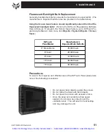
Page 60: ...Objects Screen Saver Precautions To ensure the longevity and effectiveness of the EZTouch Panel please take note of the following precautions Do not press sharp objects against the screen Do not strike the panel with hard objects Do not press the screen with excessive force Once the panel is mounted and has power applied do not place any objects over the ventilation slots This will result in heat ...

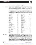
Page 61: ...ntastic E Formula 409 E Grape Juice E Heptane E Hexane E Hydrogen Peroxide N Isopropyl Alcohol E Ketchup E Lemon Juice E MEK F Methylene Chloride N Mineral Acids dilute E Mineral Acids strong G Mr Clean E Mustard G Naphtha G Phenol N Sodium Hydroxide dilute G Sodium Hydroxide strong F Sodium Hypochlorite E Spray N Wash E Tea E Toluene E Tomato Juice E Top Job E Trichloroacetic acid F Triethanolami...

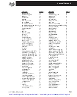
Page 62: ...rochloric Acid 5 E Hydrochloric Acid 20 F Hydrochloric Acid 35 N Hydrofluoric Acid 5 F Hydrofluoric Acid 48 N Hydrogen Peroxide 5 E Hydrogen Peroxide 30 E Hydrogen Peroxide 90 E Isobutyl Alcohol G Isopropyl Acetate N Isopropyl Alcohol E Isopropyl Benzene N Kerosene E Lactic Acid 3 G Lactic Acid 85 G Methoxyethyl Oleate N Methyl Alcohol F Methyl Ethyl Ketone N Methyl Isobutyl Ketone N Methyl Propyl...

Page 63: ...wder G Salicylic Acid sat G Salt Solutions Metallic E Silver Acetate G Silver Nitrate E Sodium Acetate sat G Sodium Hydroxide 1 N Sodium Hydroxide 50 N Sodium Hypochlorite 15 F Stearic Acid Crystals G Sulfuric Acid 6 E Sulfuric Acid 20 G Sulfuric Acid 60 F Sulfuric Acid 98 N Sulfur Dioxide Liquid G Sulfur Dioxide dry G Sulfur Salts N Tartaric Acid G Tetrahydrofuran N Thionyl Chloride N Toluene N T...

Page 64: ...tion Problem Cannot communicate with EZTouch panel from Programming Computer Action 1 Check cable ensure that it is the correct cable EZTOUCH PGMCBL and that it is properly connected at both ends 2 Check panel for power 3 Check to ensure the correct PC COM port is selected in the EZTouch Programming Software and that it is available in the PC 4 Check the COM1 setting in Setup Mode on the panel see...

Page 65: ...rd to read Adjust screen contrast control for 6 or 8 inch units 10 inch and 15 inch units have no contrast adjustment c Unit SETUP screen appears normal Unit has no user program install user program See Connections and Wiring this manual for more information Problem Display hangs when unit is powered up Initializ ing message remains on screen unit has invalid RAM memory Action 1 Remove power While...

Page 66: ...d an answer to give us a call from Monday through Friday 9 a m to 6 p m EST at the number above and we will be glad to assist you Warranty Repairs If your EZTouch Panel is under warranty contact Automationdirect com 1 770 844 4200 Out of Warranty Repairs If your EZTouch Panel is out of warranty contact AVG s Service Department for an evaluation of repair costs 1 563 359 7501 You can then decide wh...

Page 67: ...58 EZ TOUCH M Revison 4 This page intentionally left blank Artisan Technology Group Quality Instrumentation Guaranteed 888 88 SOURCE www artisantg com ...

Page 68: ...L DirectLogic PLC 15 pin D SUB DL405 RS 232C P N EZ 4CBL 1 DirectLogic PLC 25 pin D SUB DL405 350 305 DCU and all DCMs RS 232C P N EZ 4CBL 2 General Electric 90 30 and 90 70 15 pin D SUB RS 422A P N EZ 90 30 CBL Mitsubishi FX Series 25 pin RS 422A P N EZ MITSU CBL Mitsubishi FX Series 8 pin MINI DIN RS 422A P N EZ MITSU BL 1 Modicon Modbus RS 232 Modicon ModBus with RJ45 Omron C200 C500 RS 232C P ...

Page 69: ...ing pinouts for the EZTouch Panel to PLC Cables Allen Bradley SLC500 DH 485 AIC Point to Point 1 8 9 15 EZTouch Panel Female PLC Port located on bottom of unit Allen Bradley SLC500 5 01 02 03 DH 485 AIC RS 485A P N EZ DH485 CBL Artisan Technology Group Quality Instrumentation Guaranteed 888 88 SOURCE www artisantg com ...

Page 70: ... CBL Allen Bradley Micrologix 1000 1200 1500 RS 232C P N EZ MLOGIX CBL Allen Bradley PLC5 DF1 RS 232C P N EZPLC5 232 CBL 6 7 8 3 4 5 1 2 0 35 DIA 0 290 Mini Din 8 pin Male Nonstandard keying Artisan Technology Group Quality Instrumentation Guaranteed 888 88 SOURCE www artisantg com ...

Page 71: ...15 pin 250 250 1 260 06 RS 232C P N EZ 2CBL 1 DirectLogic PLC RJ 11 340 RS 232C P N EZ 3CBL DirectLogic PLC RJ 12 DL05 DL105 DL205 DL350 and DL450 RS 232C P N EZ 2CBL Artisan Technology Group Quality Instrumentation Guaranteed 888 88 SOURCE www artisantg com ...

Page 72: ...A 5 DirectLogic PLC 15 pin D SUB DL405 RS 232C P N EZ 4CBL 1 DirectLogic PLC 25 pin D SUB DL405 350 305 DCU and all DCMs RS 232C P N EZ 4CBL 2 Artisan Technology Group Quality Instrumentation Guaranteed 888 88 SOURCE www artisantg com ...

Page 73: ... Revision 4 General Electric 90 30 and 90 70 15 pin D SUB RS 422A P N EZ 90 30 CBL Mitsubishi FX Series 25 pin RS 422A P N EZ MITSU CBL Artisan Technology Group Quality Instrumentation Guaranteed 888 88 SOURCE www artisantg com ...

Page 74: ...n 4 A 7 Mitsubishi FX Series 8 pin MINI DIN RS 422A P N EZ MITSU CBL 1 Modicon ModBus RS 232 Wiring Diagram for the 984 CPU Quantum 113 CPU Artisan Technology Group Quality Instrumentation Guaranteed 888 88 SOURCE www artisantg com ...

Page 75: ...vision 4 Wiring Diagrams for AEG Modicon MICRO Series 110 CPU 311 xx 110 CPU 411 xx 110 CPU 512 xx 110 CPU 612 xx Modicon ModBus with RJ45 Artisan Technology Group Quality Instrumentation Guaranteed 888 88 SOURCE www artisantg com ...

Page 76: ...APPENDIX A EZ TOUCH M Revision 4 A 9 Omron C200 C500 RS 232C P N EZ OMRON CBL Omron CQM1 amd CPM1 Artisan Technology Group Quality Instrumentation Guaranteed 888 88 SOURCE www artisantg com ...

Page 77: ...or RS 232C P N EZ S7MPI CBL Panel PLC Port Siemens S7 MPI Adaptor RXD CTS 3 8 TXD RXD TXD 2 2 3 8 RS 232 GND RTS CTS GND 5 7 7 5 RTS 9 Pin Dsub Female 15 Pin Dsub Male Artisan Technology Group Quality Instrumentation Guaranteed 888 88 SOURCE www artisantg com ...

Page 78: ...PLCs For RS 422A and RS 485A connections we recommend Belden 9729 cable or equivalent Please Note The Termination Resistor is built in to pin 13 of EZTouch Panels Jumper pin 13 to pin 9 RXD to enable RS 422A Artisan Technology Group Quality Instrumentation Guaranteed 888 88 SOURCE www artisantg com ...

Page 79: ...IX A A 12 EZ TOUCH M Revision 4 EZTouch RS 422A Wiring Connections for Allen Bradley SLC 503 504 RS 232 Port RS 485A Artisan Technology Group Quality Instrumentation Guaranteed 888 88 SOURCE www artisantg com ...

Page 80: ...P Option Card 37 Generic Profibus DP Option Card 39 Modicon Modbus Plus 38 context sensitive onscreen help 3 Contrast 15 43 contrast adjustment feature 43 Symbols 15 pin D Sub 28 6 inch Slim Bezel models 27 DIN Clip Mounting 27 62 Pin Socket 33 35 9 pin D Sub Connector 28 A accessories 9 adjustable features 15 Allen Bradley A B DH option cards PLC Port 30 PLC Cable Wiring Diagrams Micrologix 1000 ...

Page 81: ... Clip tab 26 29 DIN Clips 15 16 27 DIP Switches EZ Ethernet 35 EZ Ethernet Option Card 35 Generic DeviceNet I O Option Card 36 Generic Ethernet IP Option Card 37 Modicon Modbus Plus Option Card 38 DirectLogic PLC Cable Wiring Diagrams 15 pin D SUB P N EZ 4CBL 1 DL40 A 5 25 pin D SUB P N EZ 4CBL 2 A 5 RJ 11 P N EZ 3CBL A 4 RJ 12 P N EZ 2 CBL A 4 VGA 15 pin P N EZ 2CBL 1 250 RS A 4 DirectLogic PLC W...

Page 82: ...ing EZTouch Programming Software 2 Installing the EZTouch Panel 15 program 2 interface boards 30 internal fuse 50 Introduction 5 L languages 7 LED 28 48 55 Configuration ERROR 33 Transmit Enable 33 LEDs Allen Bradley DH Option Card 33 DeviceNet I O Option Card 36 DH 33 36 37 39 EZ Ethernet option card 35 EZEthernet option card 35 Generic Ethernet IP Option Card 37 Generic Profibus DP Option Card 3...

Page 83: ...28 30 memory locations 7 Port 15 28 30 Wiring Diagrams 2 PLC Cable Part Numbers CBL UTICW 012 A 10 P N EZ 2 CBL A 4 P N EZ 2CBL 1 A 4 P N EZ 3CBL A 4 P N EZ 4CBL 1 A 5 P N EZ 4CBL 2 A 5 P N EZ 90 30 CBL A 6 P N EZ DH485 CBL A 2 P N EZ MITSU CBL A 6 P N EZ MITSU CBL 1 A 7 P N EZ MLOGIX CBL A 3 P N EZ OMRON CBL A 9 P N EZ S7MPI CBL A 10 P N EZ SLC 232 CBL A 3 P N EZPLC5 232 CBL A 3 PLC connector All...

Page 84: ...BL A 10 Slide Switch 7 Slim Bezel Model 11 Slim Bezel Models EZ S6M RS EZ S6M FS EZ S6M FSH 28 Software 3 special interface boards 28 SPECIFICATIONS 11 13 Specifications 6 inch Models Slim and Standard 11 8 inch 10 inch 15 inch Slim Bezel 13 8 inch and 10 inch Standard Bezel 12 all 6 inch Models 11 Status LED 28 Storage Temperature vi Stud Mounting 16 Studs 16 Switches Generic Profibus DP Option C...

Page 85: ...I 6 EZ TOUCH M Revision 4 INDEX This page intentionally left blank Artisan Technology Group Quality Instrumentation Guaranteed 888 88 SOURCE www artisantg com ...

Page 86: ...l service in house repair center WE BUY USED EQUIPMENT Sell your excess underutilized and idle used equipment We also offer credit for buy backs and trade ins www artisantg com WeBuyEquipment REMOTE INSPECTION Remotely inspect equipment before purchasing with our interactive website at www instraview com LOOKING FOR MORE INFORMATION Visit us on the web at www artisantg com for more information on ...

Reviews: