background image

62

4

O

PERATION

4.4 S

ETTINGS


IN


THE


EXTENDED


MENU

ALS

380

4.4.9

Product length

(PRDL)

A start signal can be prematurely triggered by the 
shape of the product or reflective surfaces. In such a 
case, the product length must be manually set.
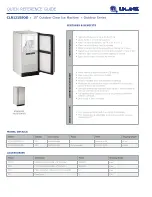
Example [67]:
If the product [D] reaches the product sensor [C], a 
start signal is sent and the machine dispenses a label. 
The recesses in the product trigger additional start sig-
nals; without the PRDL function, the product would be 
labelled several times. With the product length [A] set in 
the PRDL function, the machine ignores all start signals 
until the product has passed the dispenser head.

In the extended menu:

Call up the PRDL function.

Set the product length.

– Settings are possible in 1 mm steps:

Minimum: 5 mm
Maximum: 999 mm

Confirm the value using the ENTER key and exit the 
function.

To set the product length the same as the label dis-
tance:

Set the value for PRDL to less than 5.

– The message AUTO appears on the operator panel.
– The control system automatically sets the value for 

PRDL to the value of the label distance (LPIT). 

[67]

A

Product length

B

Label

C

Product sensor

D

Product with recesses (arrows)

A

C B

D

Summary of Contents for ALS 380

Page 1: ...ALS 380 OPERATING MANUAL Label Dispenser Article number A6392 Release 06 2005...

Page 2: ......

Page 3: ...ical data 12 Characteristic values 12 Labels 12 Ambient conditions 12 Dimensions 12 Casing 12 Electrical system 12 Control system 12 Emissions 12 2 1 4 Design versions 13 Top labeller right hand versi...

Page 4: ...ialisation INIT 45 4 2 6 If errors occur 46 4 3 Product databanks 48 4 3 1 Functions 48 4 3 2 Loading product data banks 48 Please observe 48 Activating product databanks at switch on 49 Activating pr...

Page 5: ...ration 69 4 6 2 Functions in the extended menu 70 Please observe the following 70 Calling up the extended menu 70 Applicator type APPL 70 EP cylinder dwell time APT1 71 Blowing time APT2 71 Delay time...

Page 6: ...005 Software versions ALS 380 6 1 ALS 380 HS Master 1 1 Slave 1 0 Avery Dennison reserves the right to implement modifications of structural parts compo nents and software as well as to use equivalent...

Page 7: ...ns on how to avoid or prevent the danger s The instructions must be followed WARNING A warning notice indicates risks which could result in death or serious injury of the personnel The notice contains...

Page 8: ...the directional information mentioned in the text refers to the construction of the right hand version of Top Labeller See Figure 1 for the explanation of directional information 1 Definition of direc...

Page 9: ...gramming and administration of product data bases are only to be performed by qualified and ap propriately trained personnel or by the responsible servicing technician The responsibilities for operati...

Page 10: ...eaning and maintenance The machine is not protected against splashing water Maintain the machine in a dry condition In case fluids penetrate into the machine interior immediately switch off the ma chi...

Page 11: ...red personal safety gear e g hair nets must be provided Make sure that the safety gear is used in accordance with the regulations Operating personnels obligation to exer cise care Verify flawless func...

Page 12: ...10 2 EQUIPMENT DESCRIPTION 2 1 OVERVIEW ALS 380 2 1 1 Structural elements 2 Right hand version of the ALS 380 Labeller B G C A D E I H K L M N O F J 2 EQUIPMENT DESCRIPTION 2 1 OVERVIEW...

Page 13: ...er unit move the 2D label ribbon A loop is formed in the label ribbon between the pressure roller of the un wind unit 2E and the upper braking brush 2F An ad ditional drive roller unit in the dispense...

Page 14: ...ngth at maximum dispensing speed min 16 mm max 250 mm 1 Label roll Outer diameter Core diameter max 400 mm 76 2 mm Distance from dispens ing edge to label sen sor min 20 mm Temperature Operation Stora...

Page 15: ...eyed from left to right The dispensing edge is located on the right side Side labeller right hand version Labelling from the side onto one of the product s sides 4 The products are conveyed from left...

Page 16: ...eller left hand version Labelling from the side onto one of the product s sides 6 The products are conveyed from right to left The dispensing edge is located on the left side Labeller operation is des...

Page 17: ...en the diameter of the label roll reaches a set value This sensor is required if two labellers are operating in tandem mode see chapter Operation Activation and shut down Tandem operation Adjustable d...

Page 18: ...he functions in the menu to see the previous function page upward Within a function increase the current value NEXT next function Paging through the functions in the menu to see the next function page...

Page 19: ...the machine on and off WARNING Contact with energised components can re sult in life endangering currents through the body as well as burns Voltage continues to be present in the housing even when swi...

Page 20: ...ing task settings The task specific settings can be saved in a databank If the settings are needed again after a product change it is not necessary to re input the data You only need to call up the co...

Page 21: ...nu Extended menu Product databanks Functions ON ON ON OFF OFF OFF INIT INIT PD01 VELO VELO PD02 STOD STOD PD03 POS POS PD04 POS 2 PD05 POS 3 PD06 VERT PD07 CONT PD08 E SS PD09 LPIT PD10 PRDL PD11 P_S_...

Page 22: ...ber of unlabelled products exceeds a cer tain value the machine stops Label supply If no more labels arrive at the label stop sensor 9A 10A the machine stops and sends a signal to the output to the sy...

Page 23: ...g the label roller ensure that the machine is switched off at the main switch Never switch on the machine before the label ribbon has been completely thread ed into position Remove the old backing mat...

Page 24: ...he new label roll Rotate the knurled knob counter clockwise to se cure the label roll on the unwinding spindle Also for top labeller Also secure the label roll to the dancer arm in the axial direction...

Page 25: ...abel ribbon Overview of the threading path diagram 14 Threading path diagram for label ribbon with the labels on the outside A Right hand version B Left hand version 15 Threading path diagram for labe...

Page 26: ...and drive roller unit 16D Form a loop after the drive roller unit and guide the label ribbon over the operator panel support 16F Swing the pressure roller and web brake back into position The pressur...

Page 27: ...nd through the slot in the photoelectric sensor 17B for the dispensing edge Guide the label ribbon around the dispensing edge to the drive roller unit 17C Thread the label ribbon around the drive roll...

Page 28: ...kwise until the label ribbon is under tension After a label roll is passed through the backing material roll rests firmly on the rewinding roller The spreader mechanism allows the diameter of the rewi...

Page 29: ...led thumb screws on the guide rings 19A Setting the ribbon guides Distance between label ribbon and front plate of housing 31 5 mm The label ribbon must run between the guides with as little play as p...

Page 30: ...braking brushes Mounting locations of the braking brushes In front of the operator panel support 20A On the vertical guide for the dispensing edge 20B Loosen the stud bolt 20C Align the braking brush...

Page 31: ...r unit of the unwind unit On the drive roller unit of the label feed Loosen the knurled thumb screws on the setting rings 21A Raise the pressure roller slightly and centrally align it on the label rib...

Page 32: ...A at the dispensing edge The most favourable positioning of the pressure roller unit differs depending on the application For information on adjusting the pressure roller unit the responsible servicin...

Page 33: ...de the dispenser head to the desired height and tighten the lock 23C Fine adjustment Open the upper lock 23A Rotate the spindle 23D clockwise to move the dis pensing edge downward or rotate the spindl...

Page 34: ...25A The message AUTO appears on the operator panel The machine slowly starts up and dispenses a label The label distance is automatically measured The photoelectric sensor is automatically adapted Rel...

Page 35: ...perator panel Manually initialise the material If automatic initialisation is not possible it does not generally mean there is a malfunction Man ual initialisation is often required if the proper labe...

Page 36: ...ibbon 29B The dancer arm rewinding unit 29C points down ward The unwinding drive runs for a moment until the dancer arm points upward at an angle of approx 45 The machine is now ready for operation If...

Page 37: ...product sensor sends a start signal The start signal from the product sensor triggers the dispensing of a label label feed using the set val ues for dispensing speed label distance etc The dispensing...

Page 38: ...into the centre position Rewind unit The multiple deflections with the spring loaded dancer arm act as a buffer between the label output and the rewind unit During synchronous operation the dancer ar...

Page 39: ...f the two machines indicate their respective operating states ON on the operator panel of the currently active ma chine LOCK on the operator panel of the machine in standby W__5 if the respective mach...

Page 40: ...The operator panel of this machine indicates LOCK Start dispensing labels The conveyor belt starts up The first product reach es the product sensor 35A of the activated ma chine The product sensor se...

Page 41: ...reaches the dispensing edge The machine s display changes to W__5 The other machine is automatically activated The display of the currently active machine indicates ON On the idle machine display W__...

Page 42: ...hine The indication on the operator panel changes from LOCK to ON Press the ENTER key The machine stops the operator panel indicates OFF To resume operation On the machine that is to begin labelling f...

Page 43: ...hen the NEXT 39B key is pressed Call up function The desired function can be selected by pressing the NEXT 39B and PRIOR 39A keys The function is called up by pressing the ENTER 39C key To exit the fu...

Page 44: ...e label stop position as described below Switch on the machine at the main switch In the standard menu press the NEXT 41A or PRIOR 41B key until STOD 42 is displayed on the operator panel Call up the...

Page 45: ...n Minimum 0 5 m min Maximum 80 m min ALS 380 HS to 100 m min Confirm the setting using the ENTER key and exit the VELO function Test the setting Remove the pressure roller unit optional at the dis pen...

Page 46: ...nce is shown on the operator panel in mm Set the desired distance using the NEXT or PRIOR key Settings are possible in 0 1 mm steps Minimum 10 mm Maximum 999 9 mm Confirm the setting using the ENTER k...

Page 47: ...he FEED key is pressed a label is dis pensed If the initialisation was unsuccessful The message FAIL appears on the operator panel Initiate the INIT function again or Manually initialise the material...

Page 48: ...nn is a two digit numerical code An electronic signal is issued at the same time The signal can be further processed by an external con trol system For an explanation of the warning messages and notes...

Page 49: ...numerical code An electronic signal is issued at the same time The signal can be further processed by an external con trol system For an explanation of the error messages and notes on fault eliminatio...

Page 50: ...N Erroneous settings can lead to production setbacks damage to the machine and sys tem and can even cause work related acci dents Only qualified and specially trained per sonnel or the responsible ser...

Page 51: ...machine is switched on if it was active before the last shut down of the ma chine If the machine is operated by personnel who are not authorised to work in the product databank menu Switch off the mac...

Page 52: ...Using the ENTER key save the current settings in the selected product databank Exit the extended menu using QUIT If the selected product databank already contains data The question YES appears on the...

Page 53: ...ks that contain data are shown The indicator with the last activated product data bank blinks This product databank cannot be delet ed Delete the selected product databank by pressing the ENTER key Ex...

Page 54: ...between the leading edges of the second and third label on the same product VERT Relationship between the dispensing speed and the conveyor belt speed CONT Adjust the label stop sensor E SS Distance b...

Page 55: ...Applicator optional 56 Additional functions for the applicator PDT Print delay PDWT Printer dwell time APPL Set the applicator type used APT1 Set the dwell time for the EP cylinder APT2 Dwell time fo...

Page 56: ...display Enter the password 57 The following appears on the LED display for ap prox 1 second The extended menu is active Call up function Repeatedly press the NEXT or PRIOR key until the desired functi...

Page 57: ...key and exit the POS2 function 4 4 4 Position of third label POS3 If the products are to be given three labels Distance between the leading edges of the second and third label 59A In the extended men...

Page 58: ...sponds to a ratio of 1 1 Set the desired value Possible settings 80 to 1000 corresponds to 0 8 1 to 10 1 Confirm the value using the ENTER key and exit the VERT function Example 60 The rotational spee...

Page 59: ...not be detected Instead of just one label two or more labels might be dispensed Use of a mechanical or capacitive sensor is recom mended A mechanical sensor is only of limited use at high dispensing s...

Page 60: ...sor The LED illuminates Press the NEXT key until the LED extinguishes Make note of the value displayed when the LED ex tinguishes Value of the label If the LED does not extinguish even at the lowest v...

Page 61: ...ng A single label is dispensed Check setting Press the FEED key If the setting is correct A single label is dispensed at a constant dispensing speed The label completely separates from the backing mat...

Page 62: ...number value in mm In the extended menu Call up the E SS function Input the distance value Settings are possible in 1 mm steps Minimum 12 mm Maximum 1000 mm A maximum of 15 labels can be located betw...

Page 63: ...pensed 66A The gap on the label ribbon should be automatically compensated for 66B The leading edge of the following label should rest exactly on the dispensing edge 66C After the check Check the labe...

Page 64: ...veral times With the product length A set in the PRDL function the machine ignores all start signals until the product has passed the dispenser head In the extended menu Call up the PRDL function Set...

Page 65: ...sor 68A standard setting with automatic label compensation the trailing edge of the label passes the sensor 68B without automatic label compensa tion The function also allows the use of photoelectric...

Page 66: ...hine stops Example 70 MLAB is set to value 2 The machine stops after three products in a row are not labelled The error message E__11 appears on the operator panel In the extended menu Call up the MLA...

Page 67: ...key and exit the function The printer stamp is blocking the label feed The printer stamp should first contact the la bel ribbon only after the label has come to a standstill If the printer stamp prem...

Page 68: ...uct Refer to chapter Applicator optional page 52 4 4 20 Delay time APT3 When using an EP applicator optional Delay of the signal air blow Refer to chapter Applicator optional page 52 4 4 21 Fine tunin...

Page 69: ...ed are automatically compensated for If the conveyor belt stops the label dispenser also stops The conveyor belt can stop even while a label is being dispensed The label feed is then stopped as well O...

Page 70: ...extended menu Input the calculated setting value and exit the EGRA function The setting of the electronic transmission ratio affects the dispensing speed The smaller the EGRA compensation factor the g...

Page 71: ...til it is directly in front of the product and then blows the label onto it Electro pneumatic Applicator EP Applicator The applicator uses suction to take the label from the dispensing edge Then a pne...

Page 72: ...PRIOR keys CODE appears on the LED display Enter the password 73 The following appears on the LED display for ap prox 1 second The extended menu is active Applicator type APPL Set the applicator type...

Page 73: ...Call up the APT2 function Set the desired value Settings are possible in 1 ms steps 1 7500 ms Confirm the setting using the ENTER key and exit the function Delay time APT3 When using an EP applicator...

Page 74: ...peed vN 10 m min Document the position of the label on the product Value POSN in mm Increase speed of the conveyor belt to approx 25 m min value vH Document the position of the label on the product Va...

Page 75: ...ich can lead to irrita tion Avoid contact with the skin if possible If you have sensitive skin wear gloves CAUTION Unsuitable cleaning agents can cause con siderable damage to the machine Do not use c...

Page 76: ...and edges Clean the optics of the photoelectric sensors with a soft brush or a soft tissue Braking brushes Loosen the stud bolts 75A and remove the braking brushes Remove adhesive residues Turn the b...

Page 77: ...sor Remove the knurled thumb screw 76B Remove 2 screws on the underside 77A Remove the upper part of the housing 78A Clean the sensor surfaces 78 arrows with soft lint free rags Reassemble the sensor...

Page 78: ...ing message is displayed on the operator panel As a rule the labelling operation is continued if the operator does not stop the machine If the cause of the warning message is eliminated The warning co...

Page 79: ...y affects position accu racy Reduce dispensing speed VELO if the warning message is frequently displayed for long periods For automatic dispensing speed APSF A check of the EGRA function by servicing...

Page 80: ...Replace label roll Pressure roller not closed Swing up the pressure roller on the drive roller unit s un wind unit and return it to its position pressing against the roller The pressure roller clicks...

Page 81: ...heck the label stop position STOD Check the label distance setting LPIT Check to see whether the feed motor at the dis penser head is running E__3 The photoelectric sensor in the loop space does not d...

Page 82: ...When using a printer the printing time is too long If possible decrease the printer dwell time PDWT function Start printing process before label stop PDT func tion Several labels are missing from the...

Page 83: ...s is required refer to the Service Guide ER U Software error Press the ENTER key Make note of all the information that is displayed on the control panel Make note of what happened before the error occ...

Page 84: ...label 0 mm POS 3 0000 Multiple labelling Distance between the leading edges of the second and third label 0 mm VERT 0100 Dispensing speed conveyor belt speed CONT 0035 Sensitivity of the label stop se...

Page 85: ...direction of all motors for right hand version 1 OMOD ON Machine goes into online mode operation ready after switch on 1 TAND 0000 Distance between product sensors during tandem operation 0 0 mm 1 SLE...

Page 86: ...T DATA BANKS ALS 380 Client Order Function Data bank PD01 PD02 PD03 PD04 PD05 PD06 POS POS2 POS3 VELO STOD CONT E SS LPIT PRDL P_S_ S_S_ MLAB PDT PDWT EGRA VERT APPL APT1 APT2 APT3 APT4 Date Signature...

Page 87: ...DIX 7 2 PRODUCT DATA BANKS ALS 380 Client Order Function Data bank PD07 PD08 PD09 PD10 PD11 POS POS2 POS3 VELO STOD CONT E SS LPIT PRDL P_S_ S_S_ MLAB PDT PDWT EGRA VERT APPL APT1 APT2 APT3 APT4 Date...

Page 88: ...YY MM ending machine designation ALS380 Example 040060309 ALS380 Relevant EU directives Machinery Directive 98 37 EC EMC Directive 89 336 EEC Low Voltage Directive 73 23 EEC Applicable Harmonized Sta...

Page 89: ......

Page 90: ...Avery Dennison Deutschland GmbH Postfach 1163 85385 Eching Germany Telephone 49 8165 925 0 http www machines averydennison com...

Reviews: