


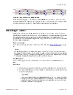


Callout
Description
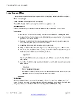
1
FI port alignment tab
2
FI cable alignment slot (Insert cable with slot facing UP and
aligned with tab on the port.)
3
FI cable connector pull tab (Ensure that the cable connector
pull tab is facing UP.)
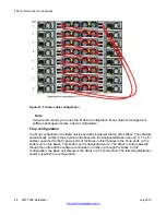
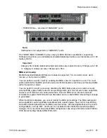
Figure 26: Installing Fabric Interconnect cables detail
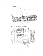
3. For Stack-mode DToR configurations, select a Base unit for the Stack. Use the Base
unit switch to configure one unit as the Base unit.
Important:
Only one unit can operate as the Base unit. Ensure that only one switch is
configured as the Base unit. The switch on all other units must be in the non-base
unit position.
4. Connect AC power.
If you assigned the Base unit and non-base units with the units powered on, you
must reset the Stack for the assignments to apply.
Installing FI cables
VSP 7000 installation
July 2013 55
Summary of Contents for VSP 7000 Series
Page 4: ...4 VSP 7000 installation July 2013 Comments infodev avaya com ...
Page 6: ...Installing an MDA 66 Appendix A Hardware reliability 67 6 VSP 7000 installation July 2013 ...
Page 28: ...Installation preparation 28 VSP 7000 installation July 2013 Comments infodev avaya com ...
Page 68: ...Hardware reliability 68 VSP 7000 installation July 2013 Comments infodev avaya com ...


