Only one unit in a Stack can operate as the Base unit. Ensure that only one switch is configured
as the Base unit.
Stack-mode DToR configurations
Each unit has a pair of FI-up and FI-down ports. You can connect the units for Stack-mode
Distributed Top-of-Rack (DToR) using a pair of FI ports, and FI cables. The Stack type and
unit numbering is dependent upon the FI cabling configuration, and the Base unit position within
the Stack. Stack-mode DToR is the default operation of the FI ports on the VSP 7000
Series.
You must always connect an FI-up port to an FI-down port, or an FI-down port to and FI-up
port on adjacent units. You must also always connect the two FI cables top to top , and bottom
to bottom on adjacent units. The following figure illustrates a simple non-redundant FI cabling
connection in a Stack of two units.
Figure 20: Non-redundant FI cabling simple diagram
Note:
The following sections describe FI down and FI up configurations, showing vertical Stack
example diagrams. The FI cabling for a Stack-mode DToR also requires an FI up or FI down
cable configuration. Stack-mode DToR is typically a horizontal deployment of one unit at the
top of each equipment rack, spanning across up to eight racks.
FI down configuration
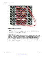
In a FI down configuration, the Base unit is physically located at the top of the Stack. The
software automatically numbers the physical units based on the designated Base unit (unit 1).
The FI cables connected to the FI-down ports of the Base unit terminates in the FI-up ports on
the next unit in the Stack, located below the Base unit. The next unit is designated unit 2. The
Stack is wired downward though the units and the software continues to number down through
the Stack. In this configuration, the Base unit discovers the Stack in a FI down direction. The
following illustration shows a typical FI down configuration.
Stack-mode DToR configurations
VSP 7000 installation
July 2013 47
Summary of Contents for VSP 7000 Series
Page 4: ...4 VSP 7000 installation July 2013 Comments infodev avaya com ...
Page 6: ...Installing an MDA 66 Appendix A Hardware reliability 67 6 VSP 7000 installation July 2013 ...
Page 28: ...Installation preparation 28 VSP 7000 installation July 2013 Comments infodev avaya com ...
Page 68: ...Hardware reliability 68 VSP 7000 installation July 2013 Comments infodev avaya com ...


