


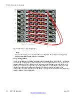


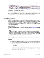


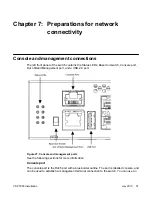


Figure 21: FI down cable configuration
Note:
Avaya recommends you to use the FI down configuration. Many network management
software packages assume a down configuration.
FI up configuration
In a FI up configuration, the Base unit is physically located at the top of the Stack. The software
automatically numbers the physical units based on the designated Base unit (unit 1). The FI
cables connected to the FI-down ports of the Base unit terminates in the FI-up ports on the
bottom unit in the Stack. This bottom unit is designated unit 2. The Stack is wired upwards
though the units and the software continues to number up though the Stack. In this
configuration, the Base unit discovers the Stack in a FI up direction. The following illustration
shows a typical FI up configuration.
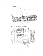
Fabric Interconnect connectivity
48 VSP 7000 installation
July 2013
Summary of Contents for VSP 7000 Series
Page 4: ...4 VSP 7000 installation July 2013 Comments infodev avaya com ...
Page 6: ...Installing an MDA 66 Appendix A Hardware reliability 67 6 VSP 7000 installation July 2013 ...
Page 28: ...Installation preparation 28 VSP 7000 installation July 2013 Comments infodev avaya com ...
Page 68: ...Hardware reliability 68 VSP 7000 installation July 2013 Comments infodev avaya com ...


