


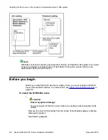


Before you begin
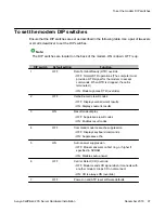
Determine which pair of consecutive slots are to contain the 201i server. The following table
identifies the Media Gateway and Media Gateway Expansion slots into which the CallPilot 201i
server can be installed:
Unit
The 201i server can be
installed in
Ineligible slots
Media Gateway
Slots 1 and 2
Slots 2 and 3
Slot 0 is dedicated to the SSC card.
Slot 4 (includes slots 5 and 6) is not
used.
Media Gateway
Expansion
Slots 7 and 8
Slots 8 and 9
Slots 9 and 10
Slot 10 is a double-wide slot. The
second half of this slot does not
have a backplane connector.
Note:
The 201i server will not function properly when installed in slots 3 and 4.
For more information about card slots, refer to the Communication Server 1000 Planning and
Installation Guide
For the logical slot numbers that you must use when you configure the Communication Server
1000 system, see
on page 77.
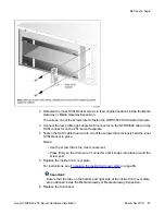
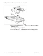
To install the 201i server inside the Media Gateway or Media Gateway Expansion
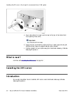
1. Ensure that no cables are connected to the slots in which you are installing the 201i
server.
2. Open the lock latches at the top and bottom of the 201i server faceplate.
Note:
When you open the top lock latch, it breaks the yellow backplane warning label
if it has not been removed. The label is not relevant for Communication Server
1000. Remove the label and continue with this procedure.
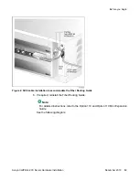
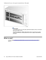
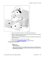
3. Slide the 201i server into an unoccupied pair of slots.
Ensure that the 201i server is positioned correctly between the slots.
When correctly inserted, the top of the 201i server is on the left. See the following
diagram:
Before you begin
Avaya CallPilot
®
201i Server Hardware Installation
December 2010 83