Automation Technology C2-2040-GigE Hardware Reference Manual Download Page 30


30  


C2-2040(HS)-GigE Camera Hardware Reference Manual Rev. 1.8 

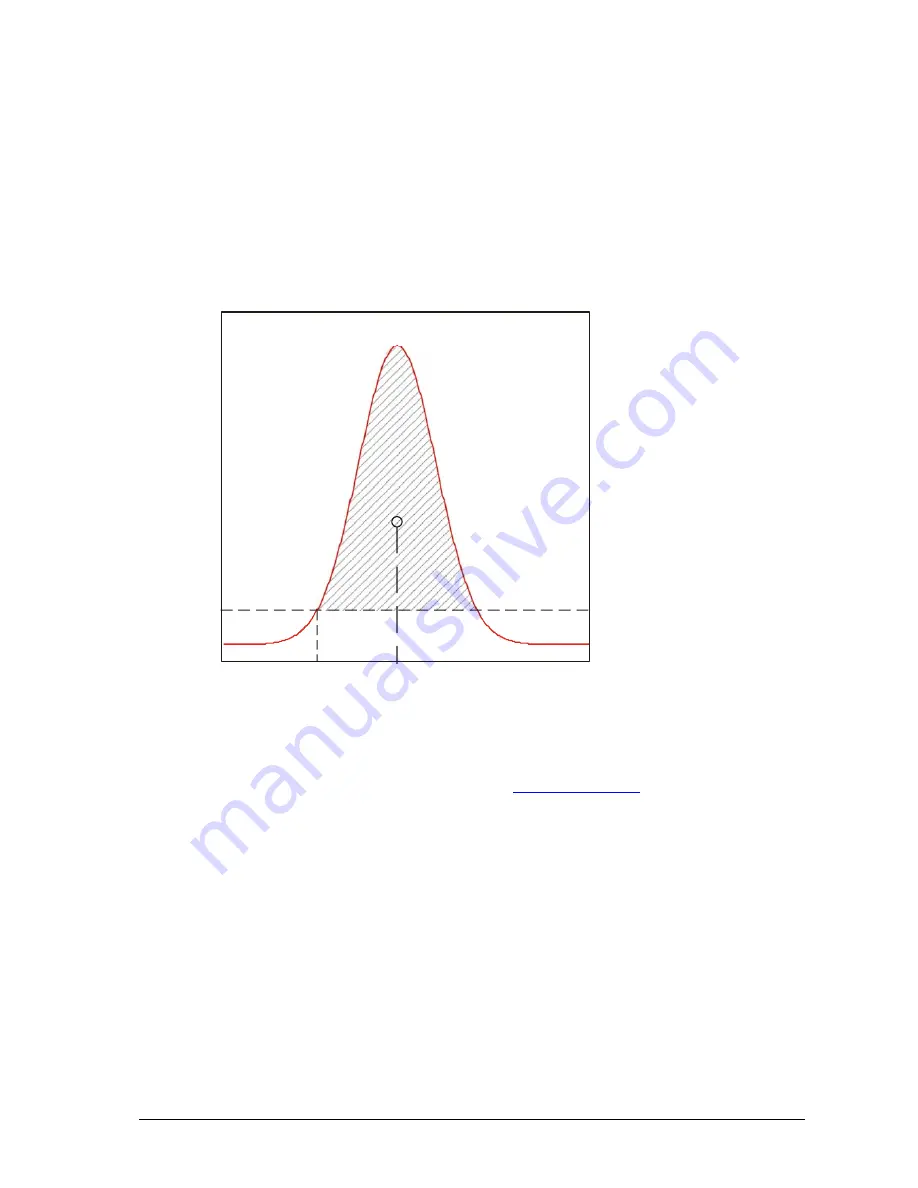
The Center Of Gravity Mode (COG) 

In this mode the center of gravity of laser beam profile is calculated. For this purpose the following 

parameters are computed: 
Position value of the left edge of laser beam profile for a given intensity threshold value P

Sum of intensity value 

I

s

 = 

 I

p

,  

Sum of first order moment 

M

s

 = 

I

* P 


AOI_TRSH

P

COG

P

L

I

S


The position value of laser line (center of gravity of beam profile) is then obtained from: 
P

COG

 = 

P

L

 + M

s

 / I

s

 .  

In addition the laser line width can be delivered over the 

Data Channel DC1

. The average intensity of 

the illumination profile can be calculated by normalising the sum of intensity value 

I

s

 with the line 

width. 
The precision of the COG calculation can be improved by enabling the smoothing mode of the FIR 
filter of the camera. 


Summary of Contents for C2-2040-GigE

Page 1: ...C2 2040 HS GigE Camera Hardware Reference Manual Rev 1 8 AT Automation Technology GmbH...

Page 2: ...r Specifications 13 C2 2040 HS GigE Camera Operational Reference 15 C2 2040 HS GigE Camera GenICam Features 15 DeviceControl 15 ImageFormatControl 15 AcquisitionControl 16 CameraControl AOIs Areas Of...

Page 3: ...nced AOI Functions 44 C2 2040 HS GigE Camera Triggering 45 Description of Profile Trigger Modes 45 Description of Modes for Triggering of Sequencer Frame and Profile Acquisition 46 The Chunk Data Mode...

Page 4: ...While care has been exercised in the preparation of this document to ensure that it is fully correct and comprehensive the owners assume no responsibility for errors or omissions Neither is any liabil...

Page 5: ...the connected image processing unit Measuring Principle The C2 camera acquires height profiles and height images based on the laser triangulation principle According to this method a laser line is pro...

Page 6: ...le the camera views the object under the triangulation angle The height resolution can be approximated Z X sin Geometry 2 The camera views the object perpendicularly to its surface while the laser lin...

Page 7: ...cted under a different angle The height resolution can be approximated Z X cos sin in case direct reflex Z X 2 sin Geometry 4 The camera views the object under an angle while the laser line is project...

Page 8: ...0 output current 20 mA Features 3D Algorithms MAX TRSH COG FIR PEAK High Speed Acquisition Full frame 340 fps High Dynamic Range Imaging Multiple Slope Multi Frame Readout Multiple AOIs Laser lines Up...

Page 9: ...on all 4 sides Example Protection Tube 202 201 100 For Lens with L 30 mm 36 mm Protective Tube Part Number Max Lens mm Max Lens length mm Camera Overall length mm 202 201 100 36 30 100 202 201 101 36...

Page 10: ...mperatures will lead to an increase of dark current noise and hence to a reduction of signal to noise ratio SNR To eliminate these effects it is often sufficient to mount the C2 sensor on a heat condu...

Page 11: ...ng the C2 Heat Sink AT provide a specially designed heat sink to improve the cooling of C2 sensors in applications lacking sufficient thermal dissipation Absolute thermal resistance for camera housing...

Page 12: ...ing temperature after power up without any additional mounted heat sink This case is very unlike because in most industrial applications the C2 sensor is mounted on a heat conductive carrier e g metal...

Page 13: ...264 mm x 5 984 mm diagonal 14 638 mm Sensor Format 2 3 Sensor ADC Resolution 10 bit Sensor Dynamic Range 90 dB with HDR Max Internal Full Frame Rate 340 fps Max External Full Frame Rate limited due t...

Page 14: ...14 C2 2040 HS GigE Camera Hardware Reference Manual Rev 1 8...

Page 15: ...egistersStreamingEnd 1 2 ICommand W Announces the end of registers streaming and perform validation for registers consistency before activating them This will also update the DeviceRegistersValid flag...

Page 16: ...itionFrameRateAbs 1 2 IFloat R The frame rate of the imager Absolute units are in Hz AcquisitionStatusSelector 1 2 IEnumeration R W Selector for AcquisitionStatus to read AcquisitionTriggerWait Acquis...

Page 17: ...loat R W Value of FIR coefficient 2 FIRC3 AT IFloat R W Value of FIR coefficient 3 FIRC4 AT IFloat R W Value of FIR coefficient 4 CameraControl ModeAndAlgorithmControl Name Rev Interface Access Descri...

Page 18: ...offset from the origin to the search AOI CameraControl ModeAndAlgorithmControl ColumnEvaluationMask Name Rev Interface Access Description ColRangeStart AT IInteger R W Column start index ColRangeEnd...

Page 19: ...uts the position value with 1 subpixel False DC2 outputs the right edge position EnableDC1TrshWidth AT IBoolean R W Controls the output in channel DC1 when TRSH algorithm is selected True DC1 outputs...

Page 20: ...nelZLevel AT IEnumeration R Volatge level of RS422 Channel Z RS422ChannelZLevel_High RS422ChannelZLevel_Low LaserPower AT IFloat R W Sets the output analog voltage of illumination control in the range...

Page 21: ...setTriggerCoordZeroPos AT IEnumeration R W Reset the Trigger Coordinate Counter at Encoder Zero Position Index Z Channel Off Index Z Off On Index Z On TriggerCoordinateCountAlways AT IBoolean R W Cont...

Page 22: ...face GevPersistentDefaultGateway 1 2 IInteger R W Persistent default gateway for the selected interface GevLinkSpeed 1 2 IInteger R Link speed in Mbps GevFirstURL 1 2 IString R NULL terminated string...

Page 23: ...R W Selects the chunk data mode OneChunkPerFrame OneChunkPerProfile EventControl Name Rev Interface Access Description EventSelector 1 2 IEnumeration R W Selector for the Event to control AcquisitionS...

Page 24: ...ength 1 2 IInteger Controls the Length of the mapping between the device file storage and the FileAccessBuffer FileOperationStatus 1 2 IEnumeration R Represents the file operation execution status Suc...

Page 25: ...ceTemperatureSelector Mainboard AcquisitionMode Continuous AcquisitionFrameCount 1 CameraMode CenterOfGravity ProfilesPerFrame 1000 ClearInvalidPos 0 PosValidationEn 0 AbsOffsetPos 0 TrshFirstFalling...

Page 26: ...0 Output1Invert 0 Output2Invert 0 SequencerMode FreeRun ProfileTriggerMode FreeRun ResetTriggerCoordZeroPos Off GevHeartbeatTimeout 3000 GevStreamChannelSelector 0 GevSCPSPacketSize 1500 GevSCPD 5000...

Page 27: ...is limited only by the sensor output rate As a matter of principle the processing speed is independent of the chosen profile mode and is determined by the AOI size In all profile modes only intensity...

Page 28: ...lculation of position value is performed with simple pixel accuracy i e the evaluation of 1088 rows delivers a position range from 0 to 1087 pixels 11 bit If there is more than one local maximum e g w...

Page 29: ...igital representation the division over 2 is not performed and thus an integer representation with one subpixel is realised The evaluation of 1088 rows delivers a position range from 0 to 2174 pixels...

Page 30: ...Sum of intensity value Is Ip Sum of first order moment Ms Ip P AOI_TRSH PCOG PL IS The position value of laser line center of gravity of beam profile is then obtained from PCOG PL Ms Is In addition t...

Page 31: ...ted and output with subpixel accuracy up to 6 subpixels In this case the threshold AOI_TRSH is used to detect the first rising edge of the derived intensity signal Valid values of AOI_TRSH range from...

Page 32: ...can be operated in a smoothing or differentiating mode FIR in smoothing mode in combination with MAX TRSH and COG algorithms FIR in differentiating mode FIR PEAK Pre defined templates with 5 7 or 9 co...

Page 33: ...ge is achieved by using a piecewise linear response The intensity of illuminated pixels which reach a certain level is clipped while darker pixels remain untouched The clipping level can be adjusted 2...

Page 34: ...ints 1 3 2 1 3 2 Intensity 1 3 2 Intensity Saturation 1 3 2 Exposure Time 100 0 Exposure Time Intensity 3 Saturation 1 2 Exposure Slope Threshold 1 3 1 2 100 0 Exposure Slope Duration 1 Knee point 1 3...

Page 35: ...e Slope Mode default mode 1 3 2 1 3 2 1 3 2 Dual Slope Mode 1 3 2 1 3 2 1 3 2 Triple Slope Mode 1 3 2 1 3 2 Integration time Intensity Saturation 1 3 2 Integration time Intensity Saturation 1 3 2 Inte...

Page 36: ...geneous reflectivity black white chessboard pattern Single Slope Dual Slope Triple Slope 0 5 10 15 20 25 30 35 40 100 200 300 400 500 600 700 800 900 1000 1100 Sensor row Intensity 0 5 10 15 20 25 30...

Page 37: ...with 2 frames when subsequent sensor images are acquired The exposure times for NDR frame 1 and 2 are depicted with It1 and It2 respectively Please note that the readout of the second frame R2 cannot...

Page 38: ...rivative of sensor intensity Not used Not used True Smoothing Smoothed sensor intensity Not used Not used MaximumIntensity False Maximum intensity of Gauss Position of rising edge of Gauss PosL Positi...

Page 39: ...of Gauss line PosL or Gauss width PosR PosL Position of center of gravity of Gauss in smoothed sensor image with 1 2N pixel resolution where N number of subpixel bits 0 6 FIRPeak True Derivative Zero...

Page 40: ...idx if EnableDC1 true write_data_of_DC1 AOI_idx if EnableDC2 true write_data_of_DC2 AOI_idx 2 NDR mode enabled NDRMode On for profile_idx 1 profile_idx ProfilesPerFrame 2 profile_idx for AOI_idx 1 AOI...

Page 41: ...f 6 profiles resulting to a frame height of 6 rows ProfilesPerFrame 10 NumAOIs 1 EmableDC0 false EnableDC1 false EnableDC2 true NDRMode Off Row Description Profile 1 Data of DC2 readout from AOI1 1 2...

Page 42: ...t from AOI2 4 Data of DC2 readout from AOI2 5 Data of DC0 readout from AOI1 2 6 Data of DC2 readout from AOI1 7 Data of DC0 readout from AOI2 8 Data of DC2 readout from AOI2 9 Data of DC0 readout from...

Page 43: ...1 EmableDC0 false EnableDC1 false EnableDC2 true NDRMode On NumberOfNDRFrames 2 Row Description Profile 1 Data of DC2 extracted from NDR1 readout from AOI1 1 2 Data of DC2 extracted from NDR2 readout...

Page 44: ...and hence the profile speed will be significantly increased due to the smaller number of pixels to readout In some cases the AOI position may not be constant and it should follow the image of laser l...

Page 45: ...Profile Acquisition 1 Profile Acquisition 2 Profile Acquisition 3 IN1 Profile Acquisition 4 2 Camera input 2 PTM2 t Profile Acquisition 1 Profile Acquisition 2 Profile Acquisition 3 IN2 Profile Acqui...

Page 46: ...of camera input 1 IN1 and stopped with rising edge of camera input 2 IN2 trigger start of sequencer frame trigger t trigger stop of sequencer When stop occurs the frame is not transmitted immediately...

Page 47: ...rising edge of camera input 2 IN2 trigger start of sequencer frame trigger t trigger stop of sequencer When stop occurs the frame is transmitted immediately over the GigE interface Using the Chunk Dat...

Page 48: ...cqInfo block per image frame in 3D mode the camera can send one ChunkAcqInfo block either per 3D frame OneChunkPerFrame or per 3D profile OneChunkPerProfile The ChunkImageInfo is the last ChunkData se...

Page 49: ...sition as soon as the stop trigger occurs and transfers the complete contents of internal image buffer Using the ChunkImageInfo data block it is possible to detect how many image rows and ChunkAqInfo...

Page 50: ...Manual Rev 1 8 XML Descriptors and Id s ChunkImageInfo Port Name FrameInfoPort ChunkID 11119999 ChunkID Port ChunkAcqInfo Port Name CameraChunkPort ChunkID 66669999 ChunkID Port ChunkImage Port Name...

Page 51: ...int frameCnt 8 11 signed int triggerCoord 12 15 unsigned char triggerStatus 16 unsigned short DAC 17 18 unsigned short ADC 19 20 unsigned char INT_idx 21 unsigned char AOI_idx 22 unsigned short AOI_ys...

Page 52: ...tion AcquisitionStart 36882 Frame Acquisition is started AcquisitionEnd 36883 Frame Acquisition is terminated TransferStart 36884 Frame transfer is started from the camera TransferEnd 36885 Frame tran...

Page 53: ...ware Reference Manual Rev 1 8 53 C2 2040 HS GigE Camera Interface The GigE Interface M12 GigE Female Connector Pin Assignment Pin No GigE Signal Name 1 BI_DC 2 BI_DD 3 BI_DD 4 BI_DA 5 BI_DB 6 BI_DA 7...

Page 54: ...7 AO LASER_AOUT Output for analog modulation of illumination device 0 5 V DC 8 VCC_EXT camera supply voltage 10 24 V DC 9 GND_EXT main camera ground 10 RS232_RX RS 232 compatible input 11 RS232_TX RS...

Page 55: ...er On Off no network cable connected Green On network connected After Network connected Green On CCP status connected Off CCP status disconnected Red On no network found no network cable connected 3 L...

Page 56: ...Data bits 8 Parity None Stopbits 1 Handshake None Sample camera boot log Bootloader build May 31 2013 16 24 31 Executing program starting at address 0x50000000 00004682 ms Camera start Start Hardware...

Page 57: ...e 1 Length 726124 00004904 ms File CMV2k4k srec Rev 1020300 Device 1 Length 726124 00004910 ms GEV Version 1 1 00004913 ms XML URL1 Local C2_2040_GigE_1 0 4 zip 8C400904 55DB 00004919 ms XML URL2 http...

Page 58: ...l signals of the C2 camera It features the following functions integrated receiver for use with differential RS422 HTL as well as single ended encoder signals direct I C interface to control laser or...

Page 59: ...5 V VIH logic 1 Voltage 3 5 V Max current 2 mA HV VIL logic 0 Voltage 7 5 V VIH logic 1 Voltage 17 0 V Outputs TTL VOL_TTL logic 0 Voltage 0 4 V VOH_TTL logic 1 Voltage 3 3 V driving capacity 4 mA HV...

Page 60: ...amera ground J201 4 VCC Supply chain of camera voltage J300 1 GND encoder ground J300 2 HZ HTL encoder index track Z J300 3 HZ HTL encoder index track Z single ended index track Z J300 4 HB HTL encode...

Page 61: ...HV OUT1 Isolated output 1 9V 24V J400 4 HV OUT2 Isolated output 2 9V 24V J400 5 OUT1 Isolated output 1 5V J400 6 OUT2 Isolated output 2 5V J400 7 IN1 Isolated input 1 5V 24V J400 8 IN2 Isolated input...

Page 62: ...with 5V and 24V DC signals The voltage level can be set over the DIP switch S400 the panel features a 1A fuse for camera protection the type of encoder signal differential or single ended can be set...

Page 63: ...operated either with TTL level or with higher voltage 9 24V DC In the latter case an external voltage supply must be connected to clamp J400 2 PWR_IO and J400 1 GND_IO or the main voltage supply of th...

Page 64: ...chain with interlock function to supply a laser with power Suitable for lasers capable of operating with camera supply voltage Interlock J201 4 SUPPLY VCC J201 3 SUPPLY GND J500 1 VCC_LASER J500 3 GND...

Page 65: ...C2 2040 HS GigE Camera Hardware Reference Manual Rev 1 8 65 Schematic of isolated digital I Os located on the C2 I O Panel...

Page 66: ...66 C2 2040 HS GigE Camera Hardware Reference Manual Rev 1 8 78mm 90mm Mount for DIN rail assembly Weight 110 g 57mm...

Page 67: ...2 HV OUT1 Not available Not available Available Available HV OUT2 Not available Not available Available Available OUT1 Available Available Available Available OUT2 Available Available Available Availa...

Page 68: ......

Page 69: ...raight M12 female connector IP64 to straight M12 male connector IP64 shielded length 5m standard 202 201 073 C2 cable for power I O and laser control straight M12 female connector IP64 to straight M12...

Page 70: ...EXT main camera ground 10 Violette RS232_RX RS 232 compatible input 11 Gray Pink RS232_TX RS 232 compatible output 12 Red Blue DO_1 OUT2 Digital Output 2 TTL 13 White Green DI_0 IN1 Digital Input 1 TT...

Page 71: ...or IP67 on camera plug to RJ45 IP20 length 3m standard 202 201 042 C2 C5 GigE cable straight M12 male connector IP67 on camera plug to RJ45 IP20 length 5m standard 202 201 043 C2 C5 GigE cable straigh...

Page 72: ...era plug unshielded length 5m 202 201 035 C2 pigtail cable for power I O and laser control straight M12 female connector IP67 on camera plug unshielded length 10m Wire assignment of C2 pigtail cable V...

Page 73: ...und for IO and Laser signals Note when using the C2 pigtail cable I O signals are not isolated The maximum voltage level is limited to 5 V The outputs are not capable of load driving IMPORTANT NOTE Wh...

Page 74: ...nor corrections 5V digital input limitation 1 3 06 01 2014 Correction GigE Pin out 1 4 28 02 2014 Minor corrections added Vlow2 and Vlow3 1 5 08 04 2014 Minor corrections 1 6 05 06 2014 Minor correcti...

Page 75: ...nTechnology de Service and Support service AutomationTechnology de In order to process your support inquiries immediately we always need the serial number of the camera a dump of configuration EEPROMs...

Page 76: ...turer be responsible for the malfunctioning we consider the right of warranty as void This is the case if the unit is modified electrically or mechanically particularly in its wiring soldering or if t...

Reviews: