background image

6

NeoSlider

TM

 - Sliding Gate Opener NES-24V3 

Owner Installation Instructions

The Automatic Technology 

NeoSlider™

 sliding gate opener is 

designed to operate most residential sliding gates. The gates 

must be in good working condition and should operate freely 

by hand.

4.1 Initial Checking

Before commencing installation of the NeoSlider™, check the 

following:

a. The gate moves freely and easily by hand for the full opening 

and closing travel.

b. The mounting point must be solidy constructed, e.g 

concrete, brick or steel, and must be capable of withstanding 

the full force applied to the gate.

c. Select a suitable location for mounting the drive unit. This 

position is usually established by fully opening the gate and 

mounting the drive unit within a suitable distance of the 

gate edge.

d. A weather-proof 240v 10 amp power outlet must be located 

within one (1) metre of the NeoSlider™ mounting point.

e. If Safety Beams are to be installed, provision for underground 

cabling should be made from one side of the gateway to 

the other.

4.2 Mounting the Drive Unit

The NeoSlider™ mounting holes are slotted for fine adjustment 

of pinion gear and gate rack alignment.  Follow the procedure 

below to ensure final adjustments can be made later. 

We recommend that four 8mm (

5

/

16

”) or 10mm (

3

/

8

”) loxins and 

bolts are used to secure the Drive Unit into position. These 

loxins usually require a 16mm (

5

/

8

”) masonry drill bit (if drilling 

concrete).


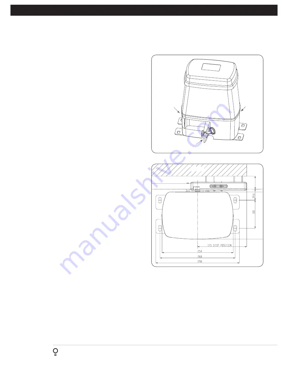
a. Prior to mounting the NeoSlider™, determine the distance 

from the gate to the outer edge of the rack (i.e. the rack 

width) and to the datum line 

(see Fig. 4.2 and Fig. 5.1)

If using an Automatic Technology plastic rack, the width is 

40mm.  If using a different brand of rack, please ensure it is 

Module 4 and then confirm the width, as this will vary.

b. Mark a line parallel to the face of the gate for the mounting 

holes.  The distance from the gate is determined by 

the formula (38mm + Rack Width).  Therefore, if using 

an Automatic Technology rack, the distance is 78mm. 


Otherwise, if using a non-Automatic Technology rack, add 

your rack width (and spacers if required) to the 38mm (see 

Fig. 4.2). 

c. Another 100mm back, mark another line parallel to that 

described in point 2 for fixing.

 (see Fig. 4.2)

d. Open the gate to the desired open position. Mark a line at 

a right angle to the gate 120-150mm from the open edge 

of the gate for the mounting holes. 

e. Then mark another line 268mm parallel to this line 


(see Fig. 4.2)

f.  Place the Drive Unit in position where the lines intersect to 

check the mounting position. If satisfied with the position, 

remove the Drive Unit. 

g. Drill the four mounting holes where the lines intersect. 

4. Drive Unit Installation

Fig 4.1

Cover 

release 

screw

Disengage lever

Cover 

release 

screw

Fig 4.2

h. Hammer the loxins into position, place the NeoSlider™ 

and fix with the four bolts.  Remember when tightening 

the bolts to allow fine adjustement of the NeoSlider™ 

later on.

4.3 Installing antenna

Mount the antenna at or above the height of the gate or 

fence (whichever is higher) for optimal reception. Do not 

cut the coaxial cable.

Summary of Contents for NES-24V3 NeoSlider

Page 1: ...NES 24V3 NeoSliderTM Sliding Gate Opener Ne Slider Doc 160056_00 Part 13428 Released 17 03 15...

Page 2: ...ergency Close SBFEC 9 8 Setting Limits 10 8 1 Setting Travel Limits 10 8 2 Setting the left right installation side settings 10 8 3 Setting close travel limit 10 8 4 Setting open travel limit 10 8 5 A...

Page 3: ...ct obstructing the gateway some force must be exerted on the object As a result the object gate and or person may suffer damage or injury Regularly check to make sure that the Safety Obstruction Force...

Page 4: ...5 06 07 08 09 10 11 12 Fig 2 1 PED N O input terminal 0V V OUT 2 optional relay module coil drive V OUT 1 N C relay contact Engage sensor microswitch input Console Previous button Console Up Open butt...

Page 5: ...DE 1 DRIVE UNIT NES 24V3 1 60188 2 TRIO CODE 4B PTX 5V2 TRANSMITTER 2 61160 3 ACCESSORY ACTUATOR PACK 2 61463 1 2 3 Set Up Items Required Automated Set Up Drive Unit and transmitter Automated Set Up w...

Page 6: ...ior to mounting the NeoSlider determine the distance from the gate to the outer edge of the rack i e the rack width and to the datum line see Fig 4 2 and Fig 5 1 If using an Automatic Technology plast...

Page 7: ...Datum line To top of pinion To bottom of rack tooth Maximum height of rack Fig 5 1 Fig 5 2 Mounting holes M4 x 10 screws and washers Actuator mounting block M4 x 30 screws Fig 5 3 5 2 Fixing limit act...

Page 8: ...system in check the power cord for damage and ensure it cannot become entangled in any moving parts 6 2 Powering up the NeoSliderTM a After checking the initial wiring apply power to the NeoSlider Th...

Page 9: ...ay Menu 7 1 for SB1 iii Ensure the Safety Beam type is set to two wires iv Press SET to accept the selection v Repeat the same process for Menu 7 2 SB2 if installed NOTE Wireless Safety Beam functiona...

Page 10: ...gate to Menu 10 h Press SET to display MENU 10 1 i Press SET two times to enter the limit setting procedure Follow LCD prompts 8 2 Setting the left right installation side settings a Select left or ri...

Page 11: ...IAN POSITION procedure See Section 12 8 7 Errors during setting of travel limit During the above procedure many error checks are preformed If an error is detected a message will be displayed indicatin...

Page 12: ...g setup Adjusting this is normally only necessitated by environmental conditions such as windy or dusty areas and areas with extreme temperature changes 9 3 Force Pressure For Close and Open Cycle Nav...

Page 13: ...IST PRESS 1 No Name OSC OFF OFF OFF PRESS PRESS IMPORTANT NOTE Only TrioCodeTM 128 Technology Transmitters are compatible with this product 10 1 Coding Transmitter Button Navigating To Menu 1 Code Tra...

Page 14: ...n activates the gate PED SWP OSC CLS STP or OPN wait for the gate to complete its cycle 11 2 Activate Remote Code Set Mode a Use a small pin to press and hold through the Coding Hole of the existing t...

Page 15: ...lt silver plastics and rare earth elements Removal of batteries and other hazardous household products from household waste facilitates the recovery of organic materials through alternative waste tech...

Page 16: ...Set Pedestrian a Press PREV to navigate to Menu 10 b Press SET MENU 10 1 is displayed c Press NEXT to go to MENU 10 3 d Press SET to enter Set Pedestrian procedure Fig 14 1 To Set pedestrian position...

Page 17: ...Beam triggered status so that the Safety Beam input must be activated again before the countdown will start As with the other Safety Beam modes the STP input will abort countdown and the OPN and SWP i...

Page 18: ...to the gate and behave differently on open cycles to that on close cycles a PressNEXTorPREVonthewallcontrolunittonavigateto Menu 4 Lock Times b Press SET to select the sub menu c Press NEXT or PREV to...

Page 19: ...odes Transmitter frequency 433 47 433 92 434 37 MHz Coding type Hopping Code No of code combinations Over 100 billion random codes Code generation Non linear encryption algorithm Transmitter battery C...

Page 20: ...lay V3 Contact dealer for support if otherwise Flat battery in transmitter Replace battery Section 12 Antenna behind structure gate or fence or not in line of sight Ensure Antenna is in line of sight...

Page 21: ...9 15 4 Menu 4 Lock Times OPEN LOCK TIME Set the time the lock is activated for on open cycles 0 0 Hold 0 5 0 1 Sec 4 1 16 1 CLOSE LOCK TIME Set the time the lock is activated for on close cycles 0 0...

Page 22: ...Selects operating polarity of OPN input Off Off 7 6 Appendix D STP INPUT N C OPERATION Selects operating polarity of STP input Off Off 7 7 Appendix D REMOTE CODE ENABLED Selects remote transmitter cod...

Page 23: ...to the required menu b Press SET to show the sub menu c Press NEXT PREV to go to the required sub menu d Press OPEN CLOSE to change parameter setting Holding the button down causes the parameter s va...

Page 24: ...RIES OV Limits Motor C O Com 1 2 MSI 1 00 Board Limits Motor C O Com 1 2 MSI 1 00 Board ATA DCB 05V2 150VA Red Black White Blue Orang e Black White Orang e Red Blue Fig C 1 This section illustrates ho...

Page 25: ...am is activated viii Ped input In this mode ped cycle is initiated when the Safety Beam is activated ix Disabled In this mode Safety Beam is disabled Menu 7 4 Second Safety Beam SB2 Response Mode Same...

Page 26: ...programmed to activate prior to the gate and behave differently on open cycles to that on close cycle ii Light Drive a light relay module can be connected on the console between V and OUT2 terminal wh...

Page 27: ...serial numbers are to be displayed The NeoSlider will then beep each time a transmission is received If the transmitter button is stored in the NeoSlider memory and has a function assigned to it a se...

Page 28: ...he OPEN CYCLE event counter with a value of 1234 When finished viewing press EXIT 1 Open Cycles 2 Close Cycles 3 PED Cycles 4 Setup Limits 5 Comm s Loss 6 Sync Faults 7 Overlaps 8 M1 Open Stall 9 M1 C...

Page 29: ...ges or press NEXT or PREV to move to the next field The example in Fig G2 shows that PED is assigned to the transmitter button 2 The transmitter in the example is transmitter number 12 which has the I...

Page 30: ...splay is provided for additional means of identification The transmitter in this example has serial number 12345 Editing A Character Field a Press NEXT or PREV to move select character b Press UP or D...

Page 31: ...to return to the list c Press SET to execute the menu s operation Fig H 1 Fig H 2 Fig H 3 Fig H 4 Menu Option Operation Code Operation location empty If the code operation is selected on an empty tran...

Page 32: ...ailer to confirm the date of purchase 9 Except for this Warranty ATA gives no warranties of any kind whatsoever whether express or implied in relation to the product and subject to paragraph 1 above a...

Reviews: