8
Owner Installation Instructions
NeoSlider
TM
- Sliding Gate Opener NES-500 / NES-800
7. Safety Beams
6. Programming The NeoSlider
TM
6.1 Common Programs
The two most common programs are;
Program
Menu’s required
Function
Section
Automated Set Up
Menu 10.1
Setting the Limits
8.1
Safety Obstruction Force
9.1 and 9.2
Menu 1
Coding the Transmitter
10.1
Automated Set Up with
Safety Beams
Menu 10.1
Setting the Limits
8.1
Safety Obstruction Force
9.1 and 9.2
Menu 1
Coding the Transmitter
10.1
Menu 3
Auto Close Times
13.2, 13.3 and 13.4
NOTE:
Fitting Safety Beams enables the Auto-Close feature to become active.
CAUTION:
Before plugging the gate control system in, check the
power cord for damage and ensure it cannot become entangled in
any moving parts
6.2 Powering up the NeoSlider
TM
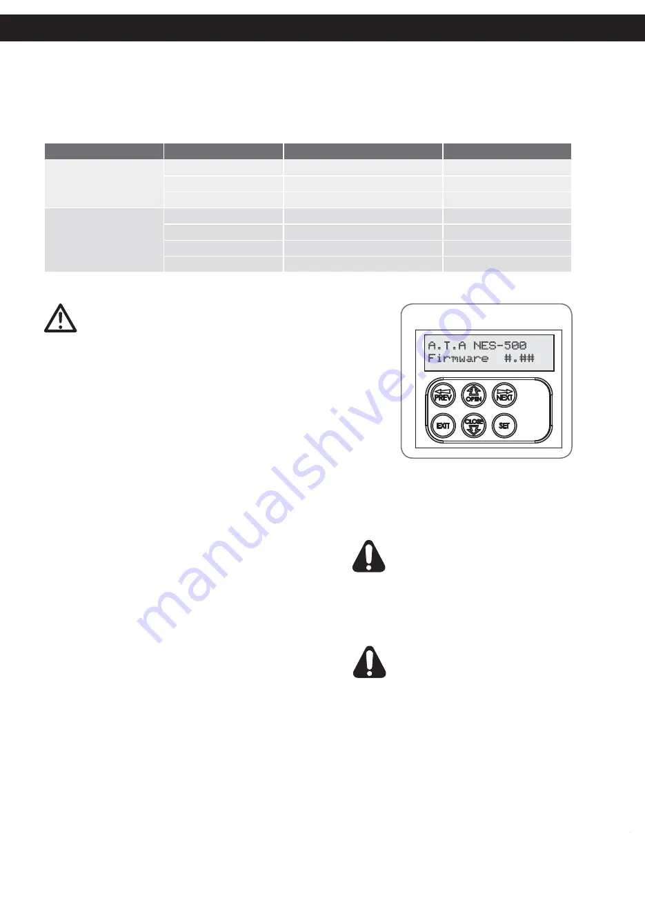
a. After checking the initial wiring, apply power to the NeoSlider™. The
controller will go through a startup sequence displaying the STARTUP
SCREEN which indicates the controller type and firmware version
(Fig. 6.2)
.
After a short delay the MAIN SCREEN will be displayed.
b. If this is the first time the NeoSlider™ has been used, the MAIN SCREEN
should indicate that the limits are not set. If the display shows that some
input is active then rectify the situation before proceeding. If a default
setting is to be changed it should be done now before setting the travel
limits.
Fig 6.2
Fig 6.1
A.T.A NES-500
Firmware #.##
Start up screen
WARNING: When using Safety Beams, the
gateway must be clear of all obstructions and
persons at all times. The location of the beams
and manner in which it is installed might not
give safety protection at all times. Check to
make sure that the height of the beam and
type used give maximum protection possible
WARNING: Tampering with Safety Beams
could result in serious personal injury and/or
property damage and will void the warranty.
7.1 Installation of Safety Beams to the NeoSlider
TM
a. Follow the Installation Manual provided with the Safety
Beam to correctly install the Safety Beam.
b. By default the NeoSlider™ will take two wire safety beams.
c. Ensure you program the NeoSlider™ to idenitfy what type
of Safety Beam or combination of Safety Beams you have
installed.
i. Press NEXT to Navigate to Menu 7
ii. Press SET to display Menu 7.1 (for SB1).
iii. Ensure the Safety Beam type is set to two wires.
iv. Press SET to accept the selection.
v. Repeat the same process for Menu 7.2 (SB2) if installed.
NOTE:
Wireless Safety Beam functionality is equivalent to 2
WIRE Safety Beams
NOTE:
The Power control for one or both three wire beams
is controlled via OUT 1 or OUT 2. To use the OUT 1, connect
black wire from SB to OUT 1. To enable power control from
OUT 1, go to Menu 7.13 and change OUT1 mode to 3 wire
SB 0V.
NOTE:
In the case that OUT 1 is used for some other function,
OUT 2 can be used to control 3 wire beams power. Connect
the black wire from SB to OUT 2, then change the OUT 2 mode
in Menu 7.14 to 3 wire SB 0V.
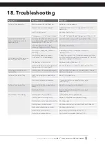
7.2 Safety Beam Failure Emergency Close
(SBFEC)
When the user finds that they are unable to move
the gate and suspect that it is due to a faulty
SAFETY BEAM they can attempt to enter Safety
Beam Failure Emergency Close mode by pressing
and holding a pre-coded button on the remote
control or OPEN/CLOSE button on the console for
more than five seconds. the gate will start closing.
See Appendix C Menu 7.16.


