


8
GDO-11v2 Ero®
Owner Installation Instructions
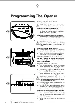
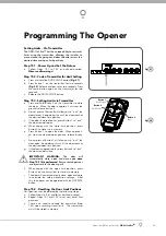
Operating Controls
01
02
03
04
05
06
07
08
09
10
11
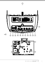
Terminal Block (Left to Right).
V+ is used to power wireless Safety Beam, external receiver etc.
SB1 fi rst Safety Beam input.
0V for Safety Beam
SB2 second Safety Beam input.
0V for Safety Beam
AUX/ O/S/C can either be used to control another device (such as alarm system etc) via the openers
remote control or a wired switch (momentary contact) can be connected to this terminal to open, stop
or close the door.
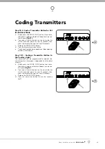
Coding Led
(red) light fl ashes when a code is being stored or when a transmitter button is pressed.
DOOR CODE
button is used for storing or erasing transmitter buttons for door operation
Door Status Led
(Yellow)
SET
button (Orange) is used during the installation phase together with the PLUS (+) and MINUS (-) buttons
to set the door limit positions. The SET button is also used to re-initialize the Opener.
OPERATE
button (Yellow) is used during installation to test the open, stop and close cycles for the
opener. The opener has to be initialised by the SET button to make the OPERATE button operable.
FORCE MARGIN SET
Button: The obstruction force margin is set automatically during installation.
The margin can be adjusted manually using the FORCE MARGIN SET button (White). Holding the FORCE
MARGIN SET button and pressing PLUS (+) or MINUS (-) buttons will increase or decrease the amount of
force. The FORCE MARGIN SET should only be used if environmental factors (wind, etc.) affect the door’s
operation.
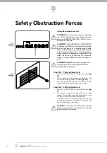
Open Limit Led
(green) the LED is very helpful during installation. It illuminates and fl ashes when the
door is opening and remains steady on when the open limit position has been reached.
PLUS
(+) button (green) is used during installation to help set the open limit position. Pressing and holding
this button will move the door in the open direction, releasing stops the door.
NOTE:
The safety obstruction detection is inoperable when the PLUS (+) button is used to move door.
Close Limit Led
(red) the LED is very helpful during installation. It illuminates and fl ashes when the door
is closing and remains steady on when the close limit position has been reached.
MINUS
(-) button (red) is used during installation to help set the close limit position. Pressing and holding
this button will move the door in the close direction. Movement stops when the button is released.
NOTE:
The safety obstruction detection is inoperable when the MINUS (-) button is used to move door.
Datum Adjust Screw
is used during limits set up to indicate the mid point of the door’s travel.
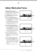
10A Fuse
Prog Input
is used to connect the Automatic Technology Handheld Programmer “PG-3” for editing
control and receiver functions, accessing diagnostic tools, and activating special features and operating
modes.
JP1 Solar Connector
the shunt must be fi tted for solar operation.
Courtesy Light
15 watts 24 volts festoon type globe is used for courtesy light.
SBCO2 J4 Standby Battery Charger Connector
the shunt must be fi tted if battery charger is not
connected.
12
13
14
15
16
17


