


26
GDO-11v2 Ero®
Owner Installation Instructions
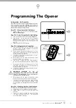
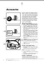
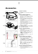
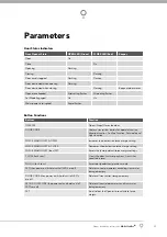
Step 21 - Auxiliary / Key Switch Connection
GDO-11v2 Ero™ has a terminal to either connect key
switch to open or close the door or use as an auxiliary
output. Connect the key switch as per diagram
Fig. 49.
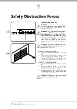
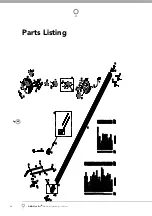
The auxiliary output can be used to control alarm or
another garage door opener with existing garage
door remote control. A valid transmission from the
pre-coded transmitter will cause the auxiliary output to
pulse for approximately 1 (one) second. The maximum
DC voltage must not exceed 35 volts DC. Maximum
current must not exceed 80 ma.
Connect the auxiliary
output as per diagram
Fig. 50.
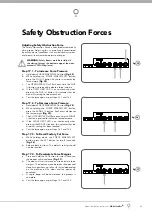
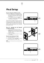
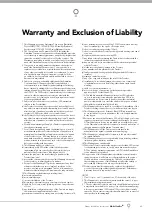
Battery Backup Installation
Step 22.1 - Connect the Battery Backup Kit
Disconnect power to the opener.Swing open the
light diffuser and controls cover. Remove screws
marked “S” in
Fig 51
and remove the main cover.
Mount the PCB support (item no 16) with two
screws (item no 12) onto the chassis. Secure the
SBC-02 charger board onto PCB support with 3
screws (item no14).
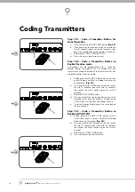
Remove the shunt plug (if fi tted) from j4 connector
on the DCB-07 control board and plug the SBC-02
charger harness (item no 9) to j4 connector.
Feed the SBY-2 battery harness (item no 10) through
the grommet on the metal plate and connect to the
terminal marked “battery” on the SBC02 as shown
in wiring diagram. refi t the main cover with screws
marked “S” in
Fig 51.
Secure the Battery Backup to GDO-11v2 Ero™
with 2 hex standoff M4 (item no 11) and 4 screws
(item no 13).
WARNING:
After Step 22.1 (f) the opener may
become active (even when power is off). This is a
result of a residual charge in the batteries.
Connect battery harnesses item 5 and 10 together
(Fig 49).
Reconnect the power.
Step 22.2 - Testing Battery Backup
Press either the OPERATE button or transmitter to
test the opener.
Whilst door is in motion, disconnect mains power
the door should continue to operate as normal.
NOTE:
Wait for the door to complete its travel.
Press the OPERATE button or transmitter to activate
the door.
Whilst door is in motion re-connect power. The
door should complete the cycle as normal.
Step 22.3 - Troubleshooting
If door stops or moves very slowly under battery power,
the batteries may be weak or have no charge. Connect
mains power and allow the batteries to charge. This may
take 24 - 48 hours to reach maximum charge capacity.
a.
b.
c.
d.
e.
f.
g.
a.
b.
c.
d.
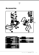
Accessories
V+
AUX /OSC
0V
SB2
0V
S B1
V+
AUX /OSC
0V
SB2
0V
S B1
External
device
Alarm, Door
opener etc.
49
fi g
50
fi g
51
fi g
S
S


