


28
GDO-11v2 Ero®
Owner Installation Instructions
53
Fig
54
Fig
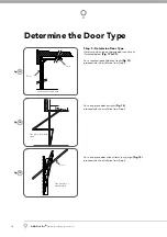
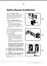
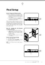
SmartSolar™ Installation
WARNING:
Do not connect batteries until Step
23.3
Step 23.1 - Mount the Charger Board
Disconnect power to the opener.
Swing open the light diffuser and controls cover.
Remove screws marked “S”
Fig 53
and lift up the
main cover.
Remove the transformer and mains power cable.
Mount the PCB support with two screws .Secure
the SOL charger board on to PCB support with 3
screws.
(Fig. 54)
.
Plug the solar charger Board’s three wire harness
(red/yellow/black) into the control board’s “SBY-3”
connector
on the control board.
Plug the Charger Board’s white one wire harness
into the control board’s “24vac in” connector.
Plug the solar shunt (supplied) onto the control
board’s “JP1” solar connector.
IMPORTANT WARNING:
Do not connect battery
or solar panel polarity incorrectly - this will result in
serious damage to components.
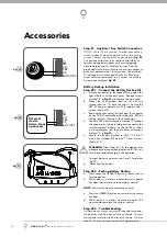
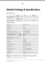
Step 23.2 - Connect the Solar Panel
Mount the solar panel as outlined in the SmartSolar™
Installation Manual.
Feed the Solar Panel’s cable through black grommet
located on the top of the metal plate.
Connect the
red wire
to the Charger Board’s
“
SOLAR+
” connector, and the
black wire
to the
“
–SOLAR
” connector
(Fig. 52)
.
WARNING:
During Step 24.3 the opener will
become active.
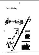
Step 23.3 - Mount & Connect the Battery
Mount the Battery Box close to the opener.
Feed the 2-core 18awg gauge cable (supplied)
through the Battery Box’s grommet.
Connect the
red wire
to the Battery Box’s “
+
” terminal,
and the
black wire
to the “
–
” terminal
(Fig. 56).
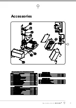
Feed the other end of the battery cable through the
Drive unit’s black grommet located on the metal
plate.
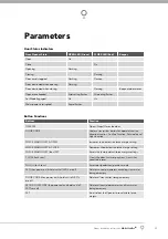
Connect the
red wire
to the Charger Board’s
“
BAT+
” connector, and the
black wire
to the “
–
BAT
” connector
(Fig. 55)
.
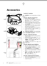
Refi t the light diffuser and main cover.
Step 23.4 - Re-setup and Test the Opener
Setup travel limits and code transmitters as per the
GDO-11v2 Ero™ instruction manual.
Press either the OPERATE button or use a transmitter
to operate the opener.
a.
b.
c.
d.
e.
f.
g.
a.
b.
c.
a.
b.
c.
d.
e.
f.
a.
b.
B
la
ck
(F
ro
m
B
at
te
ry
)
R
e
d
(F
ro
m
B
at
te
ry
)
R
ed
W
h
ite
Y
e
llo
w
B
la
ck
B
la
ck
(F
ro
m
S
o
la
r P
an
e
l)
R
e
d
(F
ro
m
So
la
r P
an
e
l)
55
Fig
Re
d W
ire
Black
Wi
re
56
Fig
Accessories
S
S


