6.05
DIRECTIONS FOR INSTALLING SOFTWARE
UPGRADE IN APi120
1)
Turn off power to the Control Module and the Food Cabinet
Wait 5 minutes for the large capacitor to discharge befo r e
working on the board. Identify and separate the three chips
b e fore beginning any wo rk . The two chips for the Control
Module are identified as LCB VX.XX and the Food Cabinet are
identified as FDB VX.XX.
2)
Remove all connectors and co vers from both control board.
3)
Observing proper anti-static procedures (grounded wrist strap)
remove the only socketed chip (U1) on the Food Driver Board
(FDB)and carefully install the new chip. Refer to the drawing
b e l ow for correct orientation of the chip. ALL CHIPS
R E P L ACED MUST BE INSTALLED CORRECTLY OR T H E Y
WILL BE DA M AG E D. Each chip being replaced has one
corner notched to identify its correct orientation, and the socket
had a corresponding notch and an arrow.
4)
R e m ove the battery from the LogiCenter Board (LCB), and
observing proper anti-static procedures (grounded wrist strap)
r e m ove the two socketed chips, and replace. R e fer to the
d rawing at right for the correct orientation of each chip.
5)
Replace both board covers, and reinstall all harnesses. Before
r e s t o ring power to machines, make sure that the Serv i c e
Connector and Power Connector are plugged to the board
correctly. Close food cabinet door.
LogiCenter Board (LCB)
Summary of Contents for 310
Page 45: ...section 5 parts This Page Intentionally Left Blank ...
Page 46: ...5 01 310 control module cabinet ...
Page 48: ...5 03 310 control module door ...
Page 50: ...5 05 310 swing panel ...
Page 52: ...5 07 310 board and power box assembly 21 24 ...
Page 54: ...5 09 310 power supply box ...
Page 56: ...5 11 320 inside door ...
Page 58: ...5 13 320 thermal window 4 6 2 8 5 12 10 11 14 1 15 13 7 16 3 17 18 ...
Page 64: ...5 19 320 baffle door assembly 8 7 6 6 4 3 5 2 1 10 9 11 ...
Page 66: ...5 21 320 baffle motor assembly 7 8 9 6 5 20 5 19 12 3 2 1 4 18 17 15 16 14 13 11 10 ...
Page 68: ...5 23 320 refrigeration assembly and components 7 6 5 12 10 13 1 4 3 11 8 ...
Page 72: ...5 27 320 junction box side wall mount 14 21 9 2 4 1 17 7 20 6 3 8 5 19 15 ...
Page 74: ...5 29 320 8 select spiral shelf 18 16 17 10 9 11 16 13 14 12 11 9 10 1 15 8 3 2 7 5 4 6 ...
Page 76: ...5 31 320 conveyor shelf 7 4 5 14 13 17 12 10 8 9 6 11 16 2 16 3 1 15 ...
Page 78: ...5 33 320 conveyor module 1 5 4 6 13 14 16 8 7 11 12 17 3 12 20 9 15 2 8 18 19 10 16 ...
Page 80: ...5 35 310 trim Top Trim or Trim Insert Trim Outside Vertical Trim Lower Horizontal Bottom Trim ...
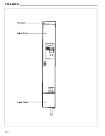
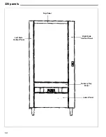
Page 82: ...5 37 310 panels Lower Panel Upper Panel Top Insert ...
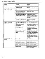
Page 89: ...6 01 trouble shooting chart ...
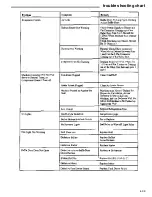
Page 90: ...6 02 trouble shooting chart ...
Page 91: ...6 03 trouble shooting chart ...
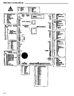
Page 94: ...6 06 electrical connections ...
Page 95: ...6 07 electrical connections P7 Default Refrigeration Jumper HI Refrigerated LO Frozen ...
Page 96: ...notes ...
Page 97: ......
Page 98: ...55 ...
Page 99: ......
Page 100: ...55 ...


