2.08
components
MasterMenu™ Keypad
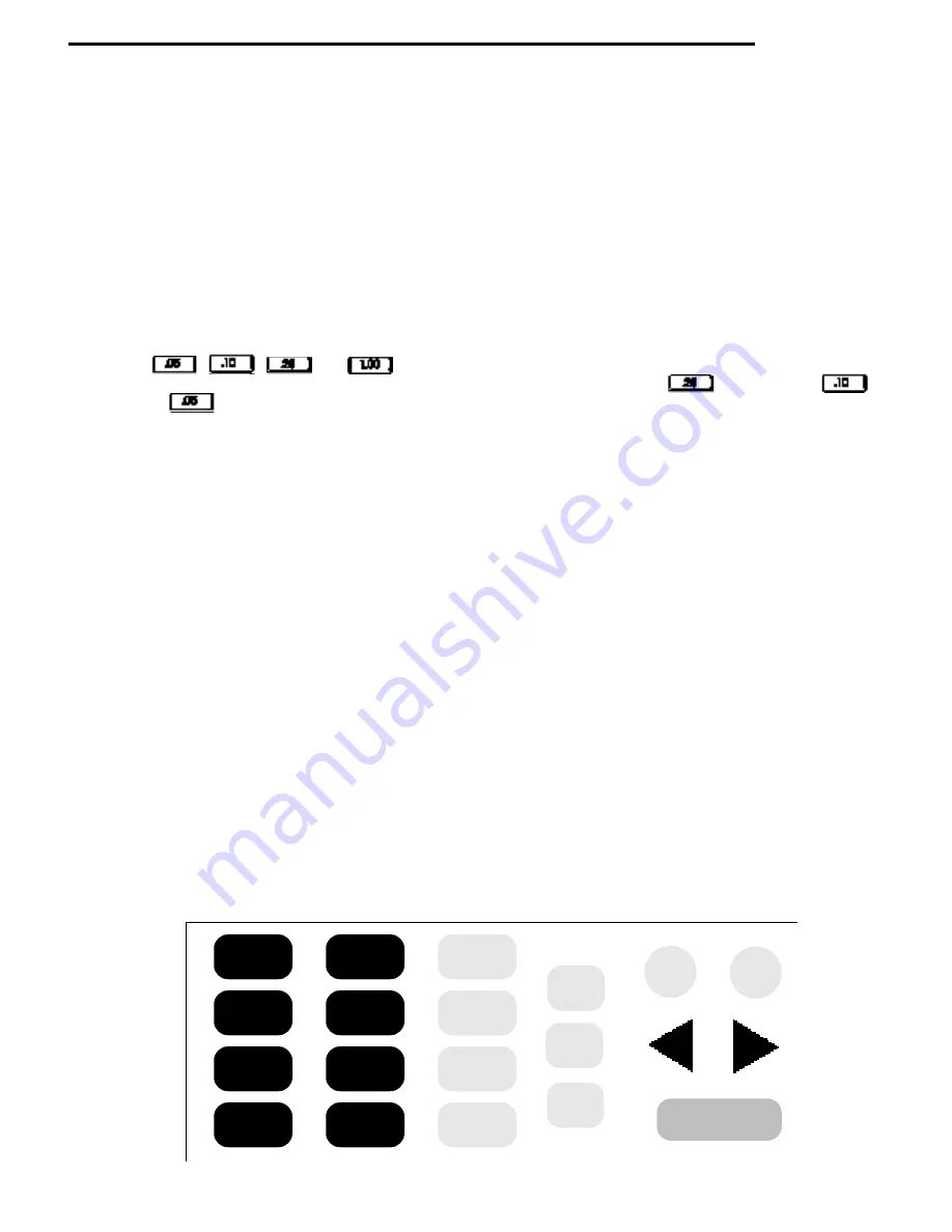
The MasterMenu™ keypad (pictured below) is located on the front of swing out panel directly below the selection
keypad. The MasterMenu™ keypad is only active when the door is open, so even in the event of vandalism to the
control bezel, no access to the control functions is permitted.The MasterMenu™ keypad consists of seven function
buttons, a
*
key, four coin payout buttons and the eight keys used to operate the MasterMenu™ functions. The entire
keypad becomes active once the machine door is opened.
Function Buttons
The seven function keys (F1-F7) are assigned to specific pre-determined menu headings, primarily for route service
personnel. See page 4.02 for specific menu heading for each of the function keys.
Pressing the
*
key before one of the function keys
¡
through
are assigned to the second level of menu headings.
Coin Payout Buttons
The four coin payout buttons are used to pay coins out of an L+ or a standard US (dummy mech).The four coin payout
buttons are , , and .The four coin payout buttons may also be used to enter pricing
information while assigning prices. For example, to enter a price of $.65, pressing the key twice, the key
once and the key once, would result in .65 appearing on the display. See the price setting section for additional
information.
The
s
key is used for exiting the current menu without making any changes prior to commitment. Note: Closing the
main cabinet door will have the same effect as if the user pressed the
s
key and causes the machine to exit the
MasterMenu™ System and return to Operational Mode.
The
e
key provides a dual purpose operation. It provides the a mechanism for entering a menu. It also provides a
means to commit insertions/modifications/deletions made in a menu item.
The
+
and
-
keys are used for incrementing and decrementing the available choices in a menu.
Note: Anywhere in this manual that the
+
or
-
keys are defined to sequence through numeric data, the front
panel may be used as an alternate input source.
The
<
and
>
keys have a dual purpose operation.They provide a means to select the menu heading immediately to
the left or right of the current menu heading.When inserting data within a menu , these keys also provide a means to
move the cursor from its current position to the position directly to its left or right.
The
y
key is used to delete the character on the current cursor position, shifting all subsequent characters to the right
of that position left by one.
The
f
key provides a mechanism to insert a character to the left of the current cursor position, shifting all characters
to the right of that position (including the current character) right by one.
Note: Depressing a function key will not cause you to enter the MasterMenu™ System.
F1
F3
F5
F7
F2
F4
F6
*
.05
.10
.25
1.00
ESC
INS
DEL
-
+
ENTER
Summary of Contents for 310
Page 45: ...section 5 parts This Page Intentionally Left Blank ...
Page 46: ...5 01 310 control module cabinet ...
Page 48: ...5 03 310 control module door ...
Page 50: ...5 05 310 swing panel ...
Page 52: ...5 07 310 board and power box assembly 21 24 ...
Page 54: ...5 09 310 power supply box ...
Page 56: ...5 11 320 inside door ...
Page 58: ...5 13 320 thermal window 4 6 2 8 5 12 10 11 14 1 15 13 7 16 3 17 18 ...
Page 64: ...5 19 320 baffle door assembly 8 7 6 6 4 3 5 2 1 10 9 11 ...
Page 66: ...5 21 320 baffle motor assembly 7 8 9 6 5 20 5 19 12 3 2 1 4 18 17 15 16 14 13 11 10 ...
Page 68: ...5 23 320 refrigeration assembly and components 7 6 5 12 10 13 1 4 3 11 8 ...
Page 72: ...5 27 320 junction box side wall mount 14 21 9 2 4 1 17 7 20 6 3 8 5 19 15 ...
Page 74: ...5 29 320 8 select spiral shelf 18 16 17 10 9 11 16 13 14 12 11 9 10 1 15 8 3 2 7 5 4 6 ...
Page 76: ...5 31 320 conveyor shelf 7 4 5 14 13 17 12 10 8 9 6 11 16 2 16 3 1 15 ...
Page 78: ...5 33 320 conveyor module 1 5 4 6 13 14 16 8 7 11 12 17 3 12 20 9 15 2 8 18 19 10 16 ...
Page 80: ...5 35 310 trim Top Trim or Trim Insert Trim Outside Vertical Trim Lower Horizontal Bottom Trim ...
Page 82: ...5 37 310 panels Lower Panel Upper Panel Top Insert ...
Page 89: ...6 01 trouble shooting chart ...
Page 90: ...6 02 trouble shooting chart ...
Page 91: ...6 03 trouble shooting chart ...
Page 94: ...6 06 electrical connections ...
Page 95: ...6 07 electrical connections P7 Default Refrigeration Jumper HI Refrigerated LO Frozen ...
Page 96: ...notes ...
Page 97: ......
Page 98: ...55 ...
Page 99: ......
Page 100: ...55 ...


