


BATTERY
18
MAINTENANCE
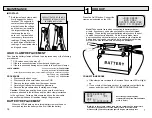
IMPORTANT:
Both jaws of each clamp must
firmly engage the battery
terminal. The copper jaw
contains the smaller gauge
wire that reads the voltage
and the silver jaw contains
the larger conducting wire
that draws the load in
each test. Jaw insulation
is necessary for accurate
readings. Damaged clamps
or loose wires will affect the
readings. Keep clamps clean
and in good repair.
CHECK OFTEN FOR LOOSE JAWS
OR DAMAGED INTERNAL PLASTIC
SHOULDER INSULATORS
LOAD CLAMP REPLACEMENT
Over time the battery clamps will need to be replaced if any of the following
are indicated:
CCA values seem to be way off.
If there is continuity between the silver and copper jaw.
If there is excessive damage or corrosion to the cables or clamps.
PART NUMBERS:
PROCEDURE
Disconnect the back cover.
Disconnect the two small wires from the PCB.
Remove the large cables from the copper busses.
Carefully pull each wire through the grommets.
Reverse the procedure when installing new clamps.
Caution
: With cables pointing down, make sure the red clamp
wires are attached to the left buss and the black clamp is attached
to the right buss. Putting a little mineral spirits on the new cable
ends will help with ease of insertion through the grommets.
1
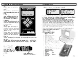
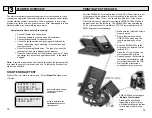
HOOK UP
Press the On/Off button: Connect the
clamps as instructed on the LCD.
Note!
Take special care when connecting to battery side ter-
minals. If necessary use a side post adapter to prevent thread
damage. When testing dual post batteries always check the post
to which the system is attached. If a load test is made from a
post connection and the alternator is mounted to side terminals a
battery load test can be completed, but a continuity problem may
still be in the side terminals when testing the alternator.
CONNECTION ERRORS
If the clamps are reversed the Reversed Connection LED will light
up.
If one or both of the clamps are not in complete contact (both the
copper and silver jaw) CHECK CONNECTIONS! will flash.
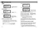
Enter the approximate battery
temperature in degrees Fahrenheit then
press (Y Enter).
Note:
Go to the setup to change temp scale to centigrade. The temperature
request only appears once for each battery tested. If the clamps are
disconnected you will be prompted again to begin a new battery test.
Positive Lead Assembly SW
458100020
Negative lead Assembly SW
458100120
Assembly includes clamp, jaws, cable, internal pick-up wire, connectors and lugs.
Black Clamp only SW
43502010
Red Clamp only SW
43501910
BATTERY REPLACEMENT
When the LCD indicates a low internal battery remove the back
cover and replace the battery with a 9 volt Alkaline battery.
JOHN DEERE
BVA 200s
SYSTEM AMALYZER
READY TO CONNECT
>ENTER BATTERY
TEMP 70F
USE +/-.
‘Y’ TO CONTINUE


