background image

1. Installation of  

AURATON 2020

Note

: During installation of the controller the power 

supply should be switched off. It is recommended to 
charge a specialist company with the installation.

1.1 A choice of proper location of the 

AURATON 2020

 controlle

Appropriate operation of the controller strongly 
depends on its location. The location without air 
circulation or in a directly insolated place results in 
inappropriate control of temperature. 

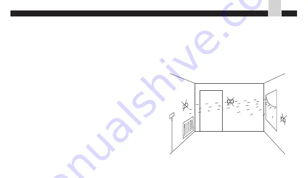
In order to ensure proper operation of the controller 
place it on an internal wall of the building (between 
the rooms). 

A place of usual sojourn should be chosen, with 
free air circulation. 

Avoid the places in the proximity of heat emitting 
equipment (TV set, heater, refrigerator) or 
subject to direct insolation. Do not locate the 
controller in a place adjacent to the door, in 
order to avoid its vibration.

1

5

0

c

m

proper location of the controller

AURATON 2020 

- Installation

32

EN

Summary of Contents for 2020

Page 1: ...aced in separate sections of the manual AURATON 2020 TX Plus enables independent modification of the protection code of the RX receiver communication The controller is programmed in the factory to 085 code number Nevertheless if any communication problem arises or another wireless temperature controller set operates in the neighbourhood the code should be changed in accordance with the instruction...

Page 2: ...ion or in a directly insolated place results in inappropriate control of temperature In order to ensure proper operation of the controller place it on an internal wall of the building between the rooms A place of usual sojourn should be chosen with free air circulation Avoid the places in the proximity of heat emitting equipment TV set heater refrigerator or subject to direct insolation Do not loc...

Page 3: ... the help of a pattern Bore two holes of the diameter of 6mm in the wall Drive the bolts and tighten the controller with screws the left hand screw longer than the right hand one Note In case of installation of a controller provided with a floor sensor pay attention to Figure inserted in Section 18 3 page 24 Note In case of a wooden wall the pins should not be used Drill the holes of 2 7mm instead...

Page 4: ...is increased and in weekends during a rest time It allows for programming with one minute accuracy At the front panel of the controller a slidable cover is located When open it gives access to the following pushbuttons the time programming pushbuttons DAY HOUR MIN the button of operation time of a heating system FILTER temperature programming pushbuttons PROG RETURN the positioning switch o 5 C ma...

Page 5: ... order to exchange the batteries Once it is removed the access to 2 R 6 batteries is opened 2 2 Display 1 The time is displayed in 24 hours system 2 English abbreviations of the days of the week indicate the current day 3 A bar indicating switching on the heating device 4 The digits indicate the currently operating program PROG 1 2 3 4 MANUAL FILTER SETPOINT BATT MO TU WE TH FR SA SU 1 2 3 4 5 6 7...

Page 6: ...m where it is installed 8 Indicator of operating hours of the heating device 9 The indicator of energy saving operation mode appears always together with the manual control indicator when the program operation is temporarily suspended in order to set any energy saving temperature level for a predetermined period of time from 1 to 7 days with one minute accuracy 10 The manual control indicator appe...

Page 7: ... PROG1 from 6 00 a m 21ºC PROG2 from 8 30 a m 21ºC PROG3 from 4 00 p m 21ºC PROG4 from 11 00 p m 17ºC MO PROG 2 0 C It means that from 6 00 a m to 8 29 am the temperature is adjusted to 21ºC from 8 30 a m to 3 59 pm the temperature is adjusted to 21ºC from 4 00 p m to 10 59 pm the temperature is adjusted to 21ºC and from 11 00 p m to 5 59 am the temperature is adjusted to 17ºC This may be graphica...

Page 8: ...oper date and time Note Longer pressing the DAY HOUR or MIN pushbutton exceeding 2 seconds causes automatic scrolling of the day hour or minute value respectively 4 3 Description of the programming function AURATON 2020 and AURATON 2020 TX RX Plus remember 8 temperatures that may be adjusted in the range from 5ºC to 27ºC with the accuracy of 0 5ºC The antifreeze temperature is constant and may be ...

Page 9: ...r to program the controller efficiently you should decide what temperatures would be required at home in the office from Monday to Friday and on Saturday and Sunday and at what time should they change A simple table proposed here would be helpful for this purpose For the period from Monday to Friday For Saturday SO program 3 program 4 program 1 program 2 Program No Hour Temperature adjustment prog...

Page 10: ... MO TU WE TH FR PROG 1 2 3 4 0C P M MO TU WE TH FR SETPOINT PROG 0 C 1 2 3 4 8 Proceed according to the points 3 and 4 9 Press PROG The display will be as follows The program indicator blinks The program 4 is to be set 10 Proceed according to the points 3 and 4 This way are set up 4 temperature thresholds and four time moments of the day in which the temperature should be changed from Monday MO to...

Page 11: ...5 times enables modification of the first program in force for Saturday 12 Proceed according to the points 3 and 4 13 Press PROG The display will be as follows the indicator of the Program 2 blinks enabling setting the second i e the last program for Saturday SA 14 Proceed according to the points 3 and 4 15 Proceed according to the points 11 to 14 in order to set the program for Sunday SU 16 Press...

Page 12: ... temperatures no need to change the switching time while programming C Programming sequence described in the point 7 3 may be changed i e the temperature may be programmed at first and afterwards the time D Programming of some or all four programs for 5 working days or for Saturday or Sunday is also possible with the same hours and different temperatures In such a case the controller shall maintai...

Page 13: ...e Afterwards the controller returns to the automatic operation program When we leave home for 3 days the room temperature may be reduced but a certain time before our return the automatic operation should be resumed In result returning home we should not even remark that the temperature was reduced during our absence We could only remark that the energy expenses are lower Example We intend to leav...

Page 14: ...nce of restoring the automatic operation strongly depends on specific properties of the object its insulation the type of heating and previous reduction of the temperature The time advance should be selected experimentally 7 Antifreeze mode This operation mode results in maintaining the room temperature amounting to 5ºC 1 Move the battery cover to the right 2 Move the slider to 5ºC This function s...

Page 15: ...showing integer number of heating hours the indicator 3 is then lit at the display In order to use the function the meter should be previously reset 1 Move the battery cover to the right 2 Press the FILTER button for at least 3 seconds until the meter displays 000 Record or remember the day of the meter resetting 8 Switching the heating device off 1 Move the battery cover to the right 2 Move the s...

Page 16: ...eless for the user simply ignore the FILTER button and indication at the display They do not affect the operation of the AURATON 2020 and AURATON 2020 TX RX Plus controllers 10 Controller sensitivity hysteresis Sensitivity of the AURATON 2020 and AURATON 2020 TX RX Plus controllers may be adjusted to 3 available levels 0 5ºC 0 25 1ºC 0 5 2ºC 1 In the factory the sensitivity level is set to 1ºC It ...

Page 17: ... Cable connection to AURATON 2020 RX Plus Note During installation of the RX controller the power supply should be switched off It is recommended to charge a specialist company with the RX installation The cable terminals are located at the rear RX controller wall There are three terminals marked by COM NO and NC This is a typical unipolar two state relay In most cases the NC terminal remains unus...

Page 18: ...ive the red diode informs whether the AURATON 2020 RX Plus controller is supplied the yellow diode indicates the radio connection with temperature controller of AURATON 2020 RX Plus 3 The switch of the additional socket 4 The additional socket designed for connecting any equipment supplied from power network Note max 5A 5 Cover of the connector 6 Supplying plug NC NO COM front back 2 1 3 4 5 6 AUR...

Page 19: ...onnected with the AURATON 2020 RX Plus receiver should cover the distance up to 100m In buildings the coverage should reach 30m which is equivalent to penetration through several stories In ferroconcrete structures the signal is strongly damped resulting in reduced coverage of the equipment Note The AURATON 2020 TX RX Plus kit is set to the 085 communication code being ready for operation upon the...

Page 20: ...20 TX Plus controllers may operate in a small area without mutual interference In case of any doubts please contact the dealer or manufacturer 15 Operation of AURATON 2020 TX RX Plus As the transmission undergoes only in one direction the AURATON 2020 TX Plus emits for security purposes a short encoded signal every minute with a view to confirming the required state of the AURATON 2020 RX Plus rec...

Page 21: ... Communication problems Setting a new communication code AURATON 2020 TX RX Plus allows for independent change of the communication protection code The controller is set in the factory to the 085 code Nevertheless should any communication problem arise or another wireless kit operates in the proximity the code should be changed according to the following instruction 1 Disconnect the AURATON 2020 R...

Page 22: ...veral times which means that the new code is recorded 5 If the changed code gives no improvement of the communication between the AURATON 2020 TX Plus controller and AURATON 2020 RX Plus receiver the code should be changed again 17 Support of the AURATON 2020 TX Plus controller The set is includes a plastic support of the AURATON 2020 TX Plus controller AURATON 2020 TX Plus Support 52 EN ...

Page 23: ...18 Connection diagrams 18 1 Diagram of direct AURATON 2020 connection to a heating device for example a gas furnace a heating device AURATON 2020 53 EN AURATON 2020 Connection diagrams ...

Page 24: ...uld be installed about 30cm above the floor level a shield pipe should be designed and laid in the hollow previously made in the wall and floor The pipe should be flushed with the mat or heating conducts min 50 cm and plugged at its end Temperature sensor should be located inside 230V yellow green protection wire Floor mat Location of a temperature sensor on the conduct the option with floor heati...

Page 25: ...18 3 Diagram of direct AURATON 2020 connection to an electric device of the power below 230V and 5A max 230V 5A max 230V AURATON 2020 a heating device 55 EN AURATON 2020 Connection diagrams ...

Page 26: ...ATON 2020 connection to a gas boiler independent on power supply without the circulation pump red electromagnetic valve of the gas boiler connector cube socket supply 230V 12V AURATON 2020 AURATON 2020 Connection diagrams 56 EN ...

Page 27: ...r of the connection cube should be removed and replaced with the receiver wires In case of any doubts please contact the dealer or manufacturer 1 2 18 5 Diagram of direct AURATON 2020 RX Plus connection to a heating device NO COM NC AUTO MAN TH PROG 0 C a heating device for example a gas furnace 57 EN AURATON 2020 TX RX Plus Connection diagrams ...

Page 28: ...st data The executing relay It is a two state self sustaining relay with For the standard setting of the micro switch slider slider 1 bottom position it has the following states 1 for active switching indicator No 7 of the display NO COM short circuited COM NC open 2 for inoperative switching indicator NO COM open COM NC short circuited Note Avoid high inductive and capacitance loads that are cond...

Page 29: ...on Saturday 2 on Sunday 6 Sensitivity of temperature control 0 5ºC 1ºC or 2ºC adjusted in the factory to 1ºC 7 Control mode Heating 8 Admissible load of the terminals 230V AC 50Hz 5A 9 Supply 2 R6 batteries alkaline ones for the TX version 10 Dimensions 154 80 30mm width height thickness 11 Operating temperature from 0 to 50ºC 12 Storage temperature from 20 to 50ºC 14 Humidity conditions from 5 to...

Reviews: