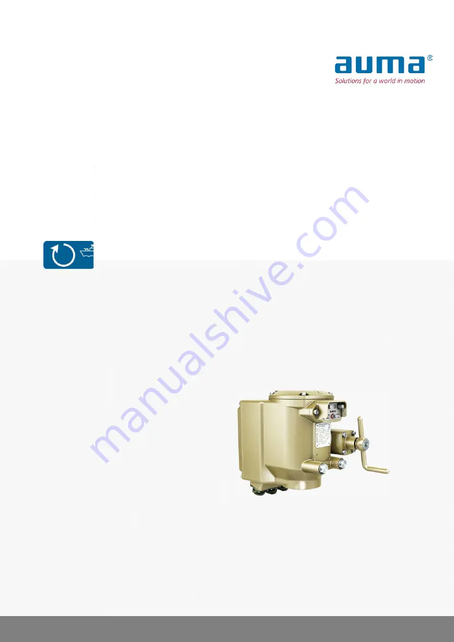
Control
Parallel
Profibus DP
→
Modbus RTU
Globe valve actuators
SVM 05.1 – SVM 07.5
SVMR 05.1 – SVMR 07.5
with integral actuator controls
Assembly, commissioning
Operation instructions
Page 1: ...Control Parallel Profibus DP Modbus RTU Globe valve actuators SVM 05 1 SVM 07 5 SVMR 05 1 SVMR 07 5 with integral actuator controls Assembly commissioning Operation instructions...
Page 2: ...on 5 1 3 Warnings and notes 5 1 4 References and symbols 7 2 Identification 7 2 1 Name plate 8 2 2 Short description 9 3 Transport storage and packaging 9 3 1 Transport 9 3 2 Storage 9 3 3 Packaging 1...
Page 3: ...et again 34 10 2 2 End position OPEN set again 35 10 3 Switch compartment open 35 10 4 Potentiometer setting 37 10 5 Mechanical position indicator set 37 10 6 Switch compartment close 38 11 AUMA CDT s...
Page 4: ...settings might present a danger to the application e g cause damage to the valve or the installation The manufacturer will not be held liable for any consequential damage Such risk lies entirely with...
Page 5: ...evel of risk Failure to observe this warning could result in death or serious injury Indicates a potentially hazardous situation with a low level of risk Failure to observe this warning may result in...
Page 6: ...er to other sections of the document which provide further information on this topic These terms are either listed in the index a heading or in the table of contents and may easily be located 6 SVM 05...
Page 7: ...ufacturer 3 Type designation 4 Order number 5 Actuator serial number 6 Speed 7 Torque range 8 Current type mains voltage mains frequency 9 Electric power motor 10 Wiring diagram number 11 Control 12 C...
Page 8: ...e When registered as authorised user you may use our AUMA Assistant App to scan the Data Matrix code and directly access the order related product documents without having to enter order number or ser...
Page 9: ...observe the following points 1 Prior to storage Protect uncoated surfaces in particular the output drive parts and mounting surface with long term corrosion protection agent 2 At an interval of approx...
Page 10: ...please refer to Actuator operation at the local controls chapter 2 Should the electrical connection not be available at the time of assembly the actuator can be operated into the required end position...
Page 11: ...2 5 SVM SVMR 07 5 F07 1 Thoroughly degrease mounting faces of output mounting flanges 2 Apply a small quantity of grease to the valve shaft 2 3 Place coupling 1 onto valve shaft 2 and secure against...
Page 12: ...according to table Table 3 Tightening torques for screws Tightening torque Nm Screws Threads Strength class A4 80 24 M8 Table 4 Tightening torques for screws valid for actuators with housing made of a...
Page 13: ...is derived from the current consumption of the actuator refer to electrical data sheet The actuators are suitable for use in current circuits with a maximum short circuit 1 phase AC current value of...
Page 14: ...resistant cables The cross sectional area of every protective earthing conductor which does not form not part of the supply cable or the cable enclosure shall in any case not be less than With mechan...
Page 15: ...oving connector for power terminals wait at least 5 seconds before touching the pins sockets 5 2 1 Mains and fieldbus cables connect Observe prior to connec tion Observe permissible cross sections of...
Page 16: ...ice to the next device Information For loop topology automatic termination is performed as soon as the actuator is connected to the power supply In case of a power failure the two RS 485 loop segments...
Page 17: ...protective earth conductor of connecting cables Start running the device only after having connected the protective earth con ductor 2 Connect protective earth conductor according to wiring diagram s...
Page 18: ...ssed safely 1 Wall bracket 2 Local controls 3 Phoenix connector with connecting cable Observe prior to connec tion Permissible length of connecting cables max 30 m We recommend using an AUMA cable set...
Page 19: ...CLOSED point to the indicator mark at cover 6 2 Indication lights Figure 13 Indication lights on local controls 1 Indication light OPEN warning fault green yellow red 2 Indication light CLOSE LOCAL se...
Page 20: ...position CLOSED CLOSE illuminated in yellow Operation mode LOCAL is active The actuator can be operated via push buttons LOCAL blinking in blue 1 Hz Setting mode for end position setting is active Se...
Page 21: ...he feedback signals via Modbus RTU can be read using the appropriate Modbus function codes For further information please refer to the Manual Device integration fieldbus Modbus 21 SVM 05 1 SVM 07 5 SV...
Page 22: ...ndwheel with five ripple ring 1 Close valve Turn crank handle handwheel clockwise Drive shaft valve turns clockwise in direction CLOSE 2 Open valve Turn crank handle handwheel counterclockwise Drive s...
Page 23: ...ands can be given either in push to run or in self retaining operation mode In self retaining mode the actuator runs to the defined end position after pressing the button unless another command has be...
Page 24: ...positioner it is possible to select between OPEN CLOSE control Fieldbus REMOTE Fieldbus CLOSE and setpoint control Fieldbus SETPOINT EMERGENCY operation An EMERGENCY operation is initiated by the Fie...
Page 25: ...r to AUMA CDT software accessories chapter 3 by means of commands via fieldbus Except the termination resistor this item can only be selected via a switch within the device For fieldbus configuration...
Page 26: ...S10 are NOT relevant Settings are defined via software parameters ON 0 9 3 Type of seating set Valve damage due to incorrect setting The type of seating must suit the valve Only change the setting wi...
Page 27: ...e manufacturer Once the set tripping torque is reached the controls automatically switch off the actuator overload protection of the valve Setting via switches Condition Switch S5 is in position OFF h...
Page 28: ...ch S5 is in position OFF hardware mode Information Baud rate parity and Modbus connection monitoring time can only be set via software parameters AUMA CDT Figure 20 Switch for fieldbus address S2 Thir...
Page 29: ...re parameters Switch S5 is in position ON software mode Setting parameters Customer settings Modbus MD1 slave address Baud rate Parity stop bit Monitoring time Default values MD1 slave address 247 Bau...
Page 30: ...the termination resistors are switched on the connection to the next fieldbus device to XK3 is automatically interrupted to avoid multiple terminations Table 13 Switch S1 functions Fieldbus terminatio...
Page 31: ...rameters Condition Switch S5 is in position ON software mode Device configuration Motor speed Speed LOCAL Speed REMOTE Speed fieldbus Description of parameters Speed LOCAL Output speed for operation v...
Page 32: ...1 11 0 4 320 9 0 2 2 510 18 0 5 6 448 15 0 3 2 742 29 0 8 640 24 0 4 0 928 38 0 11 880 35 0 5 6 1 299 55 0 16 1 280 54 0 8 0 1 856 81 0 22 1 760 77 0 9 7 2 250 100 0 28 1 2 250 100 0 9 8 Cover to cont...
Page 33: ...N the indication lights go out after travelling into opposite direction The end position detection is set incorrectly if the actuator comes to a standstill before reaching the end position the left in...
Page 34: ...ing is not permissible while the indication light is blinking in red potentiometer setting must be performed in a first step also refer to Potentiometer setting chapter Once this procedure is complete...
Page 35: ...down push button 2 for approx 3 seconds until blue indication light goes out Now the actuator can be controlled from Remote via operation commands OPEN STOP CLOSE in positions OPEN or CLOSED via setp...
Page 36: ...permissible position or the indication light blinks in red 6 times If the stroke to be set is larger than the maximum actuator stroke replace the reduction gearing selecting a unit with a higher maxim...
Page 37: ...on the cover 5 Move valve to end position CLOSED again 6 Check settings If the symbol CLOSED s no longer in alignment with mark on the cover 6 1 Repeat setting procedure 6 2 Check potentiometer settin...
Page 38: ...tings via hardware switches or via software chapter Switches and software parameters are set to the same values upon delivery factory settings Further settings via AUMA CDT software Apart from basic s...
Page 39: ...ight by operating the device in the opposite direction Fault indication 1 1 blink Thermal fault motor protection tripped Cool down wait Fault indication 2 2 blinks Signal loss of analogue input 4 20 m...
Page 40: ...voltage Risk of electric shock Disconnect device from the mains before opening Figure 24 Primary fuse on power board 12 2 2 Motor protection thermal monitoring In order to protect against overheating...
Page 41: ...and repair Dry device correctly and check for proper function 13 2 Maintenance Maintenance intervals The maintenance intervals depend on load and application conditions having a major influence on the...
Page 42: ...5 1 10 5 17 13 1 125 1 6 22 SVM SVMR 07 1 10 5 17 13 1 125 0 6 8 0 SVM SVMR 07 5 Hub does not correspond to VG 85081 other versions on request 1 Indicated weight includes globe valve actuator with con...
Page 43: ...nterface Control input signals Via Modbus RTU interface Status signals output signals Push buttons OPEN STOP LOCAL REMOTE CLOSE 2 multi colour programmable indication lights End position CLOSED yellow...
Page 44: ...h with repeat er total network cable length Max cable length segment length without repeater Baud rate kbit s approx 10 km 1 200 m 9 6 38 4 Redundant loop topology Max possible cable length of re dund...
Page 45: ...6 Without Standard Shock resistance Version 400 g Version 200 g Version 70 g Version MIL S 901D Options Sea water resistant bronze housing Corrosion protection for version made of bronze Suitable for...
Page 46: ...15 Spare parts 15 1 Globe valve actuators SVM 05 1 SVM 07 5 SVMR 05 1 SVMR 07 5 46 SVM 05 1 SVM 07 5 SVMR 05 1 SVMR 07 5 Spare parts Modbus RTU...
Page 47: ...board for 022 0 1 002 3 1 Sub assembly Board in connecting cover for 022 0 3 002 3 2 Sub assembly Power supply unit switchgear 006 0 Logic board 009 0 Sub assembly Cover 500 0 Sub assembly Coupling 5...
Page 48: ...sue Subject to changes without notice The latest versions are attached to the device upon delivery and also available for download at http www auma com 16 1 Declaration of Incorporation and EC Declara...
Page 49: ...49 SVM 05 1 SVM 07 5 SVMR 05 1 SVMR 07 5 Modbus RTU...
Page 50: ...50 SVM 05 1 SVM 07 5 SVMR 05 1 SVMR 07 5 Modbus RTU...
Page 51: ...MERGENCY operation 24 Enclosure protection 7 45 End position detection setting 33 End position detection verific ation 33 F Failure behaviour 38 Fault indications 39 Fieldbus address 28 Fieldbus cable...
Page 52: ...g 42 Self retaining local 23 38 Serial number 7 8 Service 41 Servicing 41 Setpoint control Remote SETPOINT 24 Settings for controls 25 Shock resistance 45 Short circuit protection 13 Signals 21 Size 8...
Page 53: ...el 36 93 324 666 auma fabo hu www fabo hu Falkinn HF IS 108 Reykjavik Tel 00354 540 7000 os falkinn is www falkinn is AUMA ITALIANA S r l a socio unico IT 20023 Cerro Maggiore MI Tel 39 0331 51351 inf...
Page 54: ...ran 982144545654 info itg co ir Trans Jordan Electro Mechanical Supplies JO 11133 Amman Tel 962 6 5332020 Info transjordan net AUMA JAPAN Co Ltd JP 211 0016 Kawasaki shi Kanagawa Tel 81 0 44 863 8371...
Page 55: ...55 AUMA worldwide...
Page 56: ...er GmbH Co KG P O Box 1362 DE 79373 Muellheim Tel 49 7631 809 0 Fax 49 7631 809 1250 info auma com www auma com Y005 711 003 en 1 18 For detailed information on AUMA products refer to the Internet www...