AUMA SG 04.2 Operation Instructions Manual Download Page 28

8.

Basic settings for the actuator controls

To prevent valve damage and failures during commissioning, the basic settings of
actuator controls must be verified prior to electrical actuator operation (motor
operation) and adapted in compliance with the requirements of both valve and
application.

Basic settings of the actuator controls include:

Setting hardware (switches) or software mode

Setting the type of seating

Setting the torque switching

Setting the operating time

To perform basic settings, proceed as follows:

1.

via switches (directly at the device);
For switch setting, open actuator controls cover.

2.

via AUMA CDT software (with computer/notebook, tablet);

page 6, Software

 (Software versions can be downloaded from

www.auma.com)

8.1.

Actuator controls: open/close

For changing switch settings, open actuator controls cover.

open

Electric shock due to presence of hazardous voltage!

Failure to observe this warning results in death or serious injury.

Disconnect device from the mains before opening.

Wait for 60 seconds after power cut-off prior to opening the housing.
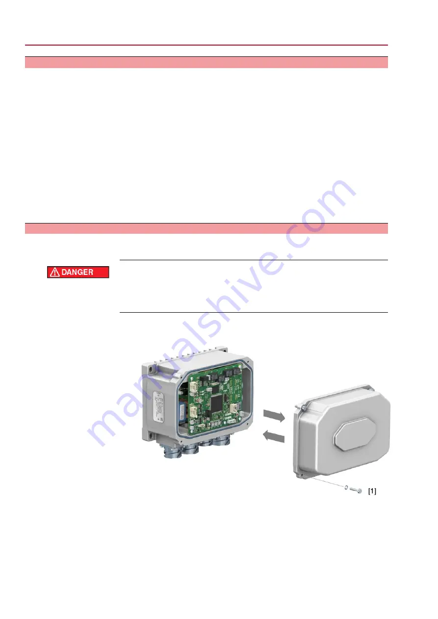
1.

Loosen 4 screws and remove cover [1] to actuator controls.

Figure 26:

2.

Clean sealing faces of housing and cover.

3.

Apply a thin film of non-acidic grease (e.g. petroleum jelly) to the sealing faces.

4.

Check whether seal is in good condition, replace seal if damaged.

5.

Apply a thin film of non-acidic grease (e.g. petroleum jelly) to the seal and insert
correctly.

6.

Place cover [1].

7.

Fasten screws evenly crosswise.

28

SG 04.2 – SG 10.2

Basic settings for the actuator controls

with actuator controls MEC 03.1

Summary of Contents for SG 04.2

Page 1: ...Part turn actuators SG 04 2 SG 10 2 with actuator controls MEC 03 1 Marine version Assembly and commissioning Operation instructions...

Page 2: ...ion 7 3 Name plate 9 4 Transport and storage 9 4 1 Transport 9 4 2 Storage 10 5 Assembly 10 5 1 Mounting position 10 5 2 Actuator mount to valve 10 5 2 1 Overview on coupling variants 10 5 2 2 Actuato...

Page 3: ...1 Mechanical position indicator 38 10 2 Indication lights on local controls of MEC 03 1 39 11 Signals output signals 39 11 1 Status signals output signals 40 12 AUMA CDT software accessories 41 13 Cor...

Page 4: ...ith the user Operation Prerequisites for safe and smooth operation Correct transport proper storage mounting and installation as well as careful commissioning Only operate the device if it is in perfe...

Page 5: ...level of risk Failure to observe this warning could result in death or serious injury Indicates a potentially hazardous situation with a low level of risk Failure to observe this warning could result...

Page 6: ...r signals Software Using the AUMA CDT software for Windows based computers notebooks or tablets actuator data can be uploaded and read settings can be modified and stored With the AUMA Cloud we provid...

Page 7: ...Name of manufacturer 2 Address of manufacturer 3 Type designation 4 Order number 5 Serial number 6 Operating time 7 Maximum torque 8 Type of lubricant 9 Permissible ambient temperature 10 Current at...

Page 8: ...r for any product inquiries On the Internet at http www auma com Service Support myAUMA we offer a service allowing authorised users to download order related documents such as wiring diagrams and tec...

Page 9: ...f or on a wooden pallet Cover to protect against dust and dirt Apply suitable corrosion protection agent to uncoated surfaces Long term storage For long term storage more than 6 months observe the fol...

Page 10: ...gs or couplings with pilot bore must be machined to match the valve shaft prior to mounting the actuator to the valve e g with bore and keyway two flat or square bore Assemble valve and actuator in th...

Page 11: ...coupling 1 Coupling 2 Valve shaft 3 Grub screw 4 Clamping washer and screw with curved spring lock washer Figure 9 Mounting positions for coupling Table 2 Mounting position of the coupling within fitt...

Page 12: ...rotate handwheel until bores line up 7 2 If required shift actuator by one tooth on the coupling 8 Fasten actuator with screws Information We recommend applying liquid thread sealing material to the...

Page 13: ...tuator refer to name plate We recommend refraining from using residual current devices RCD However if an RCD is used within the mains the residual current device must be of type B Consider length and...

Page 14: ...voltage XG2 Control and signalling XG3 Motor control XG4 Signals to and from the actuator XA1 Motor XA2 Actuator signals The permissible cable length between MEC 03 1 actuator controls and the actuato...

Page 15: ...wer plug to actuator XG4 17 contacts socket for signal connector to the actuator Figure 13 Connections to MEC 03 1 compatible with MEC 02 1 XG1 5 contacts socket for power plug power supply XG2 17 con...

Page 16: ...bles and wires to the connector refer to the enclosed wiring diagram For further data such as terminal cross sections cable diameters and tools e g crimping pliers refer to separate Technical data ITT...

Page 17: ...ction to external protective earth conductor of connection cable Power the device only once the protective earth conductor has been connected Table 4 Terminal cross sections and earth connection tight...

Page 18: ...al controls Figure 16 MEC 03 1 actuator controls with local controls option During motor operation the actuator may be operated from LOCAL via the push buttons of local controls 18 SG 04 2 SG 10 2 Ele...

Page 19: ...n Information The swing angle set in the factory e g 90 as well as the setting range e g 82 to 98 is indicated in the order related technical data sheet The swing angle can be freely adjusted within t...

Page 20: ...PEN set Information In general the end stop OPEN does not have to be set 1 Remove screw plug 1 2 Move valve to end position OPEN with crank handle handwheel 3 If the valve end position is not reached...

Page 21: ...m the setting of these sub assemblies Open 1 Loosen screws 2 and remove cover 1 from the switch compartment Close 2 Clean sealing faces of housing and cover 3 Check whether O ring 3 is in good conditi...

Page 22: ...been changed the end position detection has to be readjusted Two LEDs are available for setting 7 3 1 Setting for clockwise closing The following description is only valid for clockwise closing i e dr...

Page 23: ...ition OPEN 8 Operate valve exactly to end position OPEN If the green LED is illuminated end position detection OPEN has been correctly set If the green LED is not illuminated or only flickering end po...

Page 24: ...t again The setting disc should be positioned in the middle between illumination and going out of the green LED 5 After setting end position CLOSED Hold setting disc tight and tighten both screws 1 6...

Page 25: ...asuring range The measuring range only has to be readjusted if the swing angle set in the factory has been enlarged Setting elements The RWG is housed in the actuator switch compartment The switch com...

Page 26: ...end position CLOSED anew and check minimum value 4 1 mA If necessary correct the setting 7 5 Mechanical position indicator set Figure 24 Position indication in end position CLOSED pointer perpendicula...

Page 27: ...Further information on indication page 37 Mechanical position indicator 27 SG 04 2 SG 10 2 with actuator controls MEC 03 1 Commissioning...

Page 28: ...re versions can be downloaded from www auma com 8 1 Actuator controls open close For changing switch settings open actuator controls cover open Electric shock due to presence of hazardous voltage Fail...

Page 29: ...changed via AUMA CDT software OFF 1 Software mode sliding switch at white dot Settings of switches S2 through S4 and S6 through S10 are NOT relevant Settings are defined via software parameters ON 0...

Page 30: ...e Limit Setting values Limit Limit seating in end positions Torque Torque seating in end positions 8 4 Torque switching set Valve damage due to excessive tripping torque limit setting The tripping tor...

Page 31: ...0 35 3 320 160 80 40 4 360 180 90 45 5 400 200 100 50 6 440 220 110 55 7 500 250 125 63 8 500 250 125 63 9 Setting via software parameters AUMA CDT Condition Switch S5 is in position ON software mode...

Page 32: ...Motor is operating in stepping mode 1 Setting via software parameters AUMA CDT Motor speed and thus actuator operating time can be modified by means of the software parameters described below Contrar...

Page 33: ...t via the Speed REMOTE software parameter Table 11 Beispielwerte zur Einstellung f r Baugr en SG 04 2 05 2 07 2 Operating time Output drive s Speed Motor rpm Output speed via AIN1 Speed I O interface...

Page 34: ...indrical grip standard 2 Crank handle with conical grip 3 Handwheel with five edge ring 4 Handwheel with five ripple ring 1 Close valve Turn crank handle handwheel clockwise Drive shaft valve turns cl...

Page 35: ...e setpoints e g 0 4 20 mA Change over between OPEN CLOSE control and setpoint control For actuators equipped with positioner it is possible to select between OPEN CLOSE control REMOTE OPEN CLOSE and s...

Page 36: ...and wear protective gloves Activate operation mode LOCAL Hold down push button 2 for approx 3 seconds until the indication light 4 is blinking in blue If the right indication light is blinking in blue...

Page 37: ...position OPEN or CLOSE has been reached Perform the position indicator setting to match the valve Refer to page 26 Mechanical position indicator set Table 13 Valve position setting with regard to the...

Page 38: ...position OPEN OPEN illuminated in green The number of blinking signals indicates the number of fault signal Refer to Corrective action chapter Fault blinking in red Table 15 Indication light 2 default...

Page 39: ...utputs Designation of output contact in AUMA CDT software Designation of output contacts in wiring dia gram Signal DOUT 2 End position OPEN K 1 End position OPEN Signal DOUT 1 End position CLOSED K 2...

Page 40: ...vice cable is required Read perform basic settings via AUMA CDT software Basic settings at the device in actuator controls made via switches are read only via AUMA CDT on delivery and cannot be modifi...

Page 41: ...Signal loss of analogue input 4 20 mA Fault indication 3 3 blinks Operation mode DISABLED Operation via the local controls is disabled Enable local controls function Fault indication 4 4 blinks Fault...

Page 42: ...logic board The fuses become visible when removing the cover to the actuator controls page 28 Actuator controls open close If a fuse is defective the power board has to be replaced Figure 37 Primary f...

Page 43: ...ques as indicated in chapter Assembly When rarely operated Perform test run For enclosure protection IP68 After submersion Check actuator In case of ingress of water locate leaks and repair Dry device...

Page 44: ...waste disposal of the disassembled material or for sep arate recycling according to materials Observe the national regulations for waste disposal 44 SG 04 2 SG 10 2 Servicing and maintenance with act...

Page 45: ...st 4 Indicated weight includes part turn actuator with electrical connection in standard version unbored coupling and handwheel crank handle 5 Features and functions of actuator Short time duty S2 15...

Page 46: ...ductors or relay outputs are available each with max 30 V 1 A switching power They are preassigned with the signals as indicated below Status signals output signals Variants of semi conductor output t...

Page 47: ...dulating duty is not possible during continuous immersion Enclosure protection according to EN 60529 Pollution degree 4 when closed pollution degree 2 internal Pollution degree according to IEC 60664...

Page 48: ...her information Electromagnetic Compatibility EMC 2014 30 EU Low Voltage Directive 2014 35 EU Machinery Directive 2006 42 EC EU Directives 48 SG 04 2 SG 10 2 Technical data with actuator controls MEC...

Page 49: ...16 Spare parts 16 1 Part turn actuator SG 04 2 SG 10 2 49 SG 04 2 SG 10 2 with actuator controls MEC 03 1 Spare parts...

Page 50: ...no Sub assembly Cover 500 0 Sub assembly Coupling 525 0 Screw plug 539 0 Sub assembly Protective earthing 541 0 Sub assembly Crank handle with cylindrical grip 542 0 1 Sub assembly Crank handle with...

Page 51: ...51 SG 04 2 SG 10 2 with actuator controls MEC 03 1...

Page 52: ...52 SG 04 2 SG 10 2 with actuator controls MEC 03 1...

Page 53: ...tion 7 8 47 End position detection verific ation 22 End stops 19 F Fault indications 41 Flange size 8 Fuses 41 H Housing material 45 I Indication lights 38 Indications 37 Inspection certificate 8 Insu...

Page 54: ...T 35 Shock resistance 47 Short circuit protection 13 Signals 39 Size 8 Software 29 40 Spare parts 49 Standards 4 Storage 9 Supply networks 13 Support 43 Swing angle 19 45 Switch S5 MODE 40 T Technical...

Page 55: ...55...

Page 56: ...er GmbH Co KG P O Box 1362 DE 79373 Muellheim Tel 49 7631 809 0 Fax 49 7631 809 1250 info auma com www auma com Y009 142 003 en 1 20 For detailed information on AUMA products refer to the Internet www...

Reviews: