background image

Version 5.8 

51 

June 2009 

Installation Manual 


3. Configuring the Device 


Notes:  


Before you can load an 

ini 

or any auxiliary file, you must first load a 

cmp


file.  


When you activate the wizard, the rest of the Web interface is 
unavailable. After the files are successfully loaded, access to the full Web 
interface is restored. 


You can schedule automatic loading of these files using HTTP, HTTPS, 
FTP, or NFS (refer to the 

Product Reference Manual

). 


¾


To use the Software Upgrade Wizard: 

1. 

Stop all traffic on the device (refer to the note above). 

2. 

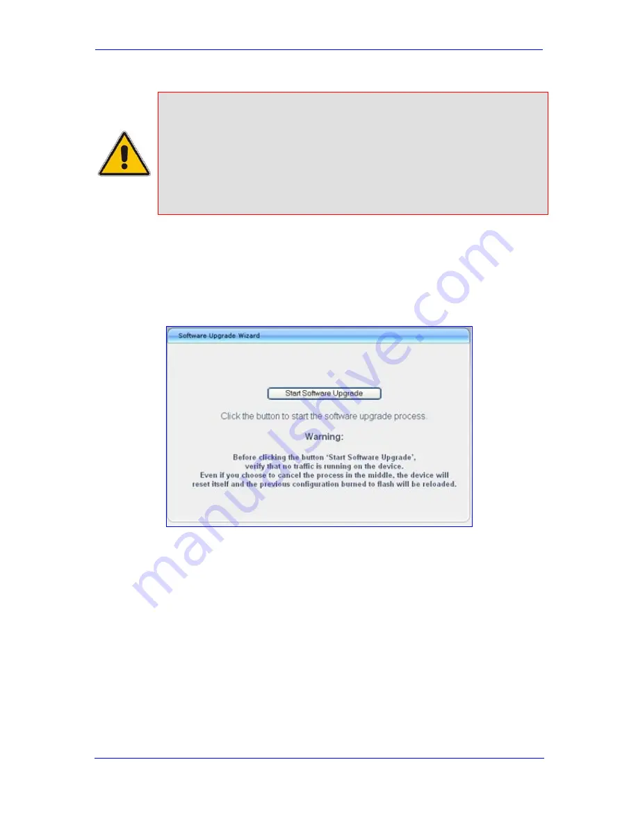
Open the 'Software Upgrade Wizard' (

Management

 tab > 

Software Update

 menu > 

Software Upgrade Wizard

); the 'Software Upgrade Wizard' page appears. 

Figure 


3-9: Start Software Upgrade Wizard Screen 


3. 

Click the 

Start Software Upgrade

 button; the 'Load a CMP file' Wizard page appears. 

Summary of Contents for Mediant 1000

Page 1: ...Document LTRT 83505 June 2009 Installation Manual Version 5 8 ...

Page 2: ......

Page 3: ... to PC 25 2 4 10 Connecting to Power 26 2 5 Maintenance 27 2 5 1 I O Module Slot Assignment 27 2 5 2 Replacing Modules 28 2 5 3 Inserting Modules into Previously Empty Slots 30 2 5 4 Replacing the Air Filter 30 3 Configuring the Device 33 3 1 Assigning an IP Address 33 3 1 1 Assigning an IP Address using HTTP 34 3 1 2 Assigning an IP Address using BootP 35 3 1 3 Assigning an IP Address using the V...

Page 4: ...Installation Manual 4 Document LTRT 83505 Mediant 1000 4 Monitoring the Device 57 4 1 Front Panel LEDs 57 4 2 Web Interface 58 4 2 1 Viewing Alarms 59 4 2 2 Viewing Channel Status 60 ...

Page 5: ...ply Module 26 Figure 2 16 Mediant 1000 Front Layout 27 Figure 2 17 Recommended Priority Module Slot Assignment 28 Figure 2 18 Module Orientation in Chassis Top and Bottom Row Slots 29 Figure 2 19 Slightly Extracted Fan Try Unit 31 Figure 2 20 Fan Tray with Filter Removed 31 Figure 3 1 Enter Network Password Screen 34 Figure 3 2 BootP Client Configuration Screen 36 Figure 3 3 Enabling Channels in T...

Page 6: ...Table 3 1 Default IP Addresses 33 Table 3 2 Configuration Parameters Available via the Voice Menu 38 Table 3 3 Auxiliary Files Descriptions 54 Table 4 1 Analog I O FXS FXO Modules LEDs Description 57 Table 4 2 E1 T1 PRI I O TRUNKS Modules LED Description 57 Table 4 3 BRI I O Modules LED Description Applicable only to SIP 58 Table 4 4 Power Supply Module LED Description 58 Table 4 5 CPU Module LEDs...

Page 7: ...eb site or on any other electronic copy all cross references are hyperlinked Click on the page or section numbers shown in blue to reach the individual cross referenced item directly To return back to the point from where you accessed the cross reference press the ALT and Å keys Trademarks AudioCodes AC AudioCoded Ardito CTI2 CTI CTI Squared HD VoIP InTouch IPmedia Mediant MediaPack NetCoder Netra...

Page 8: ...connect FXO ports to the Public Switching Telephone Network PSTN Warning FXO ports are considered to be TNV 3 FXS ports are considered to be TNV 2 Notes FXO Foreign Exchange Office is the interface replacing the analog telephone and connects to a Public Switched Telephone Network PSTN line from the Central Office CO or to a Private Branch Exchange PBX The FXO is designed to receive line voltage an...

Page 9: ...kly setting up hardware and software configuration the device for the first time The flowchart below summarizes these required steps Prior knowledge of IP networking is recommended Figure 1 1 Summary of Steps for Installing the Device Note For detailed information on how to fully configure the device refer to the device s User s Manual ...

Page 10: ...Installation Manual 10 Document LTRT 83505 Mediant 1000 Reader s Notes ...

Page 11: ...stalled or serviced by qualified service personnel 2 1 Physical Description This section provides a physical description of the device s front refer to Front Panel on page 11 and rear panels refer to Rear Panel on page 14 The device is designed with a 19 inch industrial platform chassis 1U high and 13 8 inch deep The device supports a scalable modular architecture that includes the following repla...

Page 12: ...ut only supports indoor protection To enable ground start signaling use the ini file parameter GroundKeyDetection refer to the device s User s Manual FXS Optional FXS module applicable only to SIP The device can house up to six FXS modules Each module provides four RJ 11 ports Therefore up to 24 FXS ports i e 6 modules x 4 ports are supported Note The FXS modules support both loop and ground start...

Page 13: ...e you are advised to connect each power supply unit to a different AC supply circuit 6 Power 2 Main Power Supply module refer to the above description 7 Schematic Extractable Fan Tray module with a schematic displayed on its front panel showing the chassis slot numbers The Fan Tray module cools the device s components For additional information refer to Replacing the Air Filter on page 30 CPU Enla...

Page 14: ...r modules i e the iPMX and HDMX modules For information on the OSN Server installation refer to the device s User s Manual 2 2 Unpacking Package Contents Follow the procedure below for unpacking the carton in which the device is shipped To unpack the device 1 Open the carton and remove packing materials 2 Remove the chassis from the carton 3 Check that there is no equipment damage 4 Ensure that in...

Page 15: ...p Mounting The device can be mounted on a desktop by attaching the four anti slide bumpers supplied to the underside of the device Once you have attached these bumpers simply place it on a desktop in the desired position Figure 2 3 Attached Rubber Foot on Underside of Chassis To attach the anti slide rubber bumpers to the device 1 Flip the device over so that its underside faces up 2 Locate the fo...

Page 16: ...it rack assembly the operating ambient temperature of the rack environment may be greater than room ambient temperature Therefore consideration should be given to installing the equipment in an environment compatible with the maximum ambient temperature Tma of 45 C 113 F Reduced Air Flow Installation of the equipment in a rack should be such that the amount of air flow required for safe operation ...

Page 17: ... of the device to the frame of the rack To install the device in a rack without shelves 1 Position the device in a 19 inch rack and align the front and rear refer to note below bracket holes to the holes of your choosing in the vertical tracks of the 19 inch rack 2 Use standard 19 inch rack bolts not provided to fasten the brackets to the frame of the rack Note If you are assembling the rear brack...

Page 18: ...BRI ports refer to Connecting to ISDN BRI Lines on page 22 applicable only to SIP Optional Connecting the E1 T1 trunks refer to Connecting to E1 T1 Trunks on page 22 Optional Connecting the E1 T1 trunks for PSTN Fallback refer to Connecting to E1 T1 Trunks for PSTN Fallback on page 23 Optional Connecting the Dry Contact Relay Alarm System refer to Connecting to Dry Contact Relay Alarm System on pa...

Page 19: ...ting to IP Network The device s CPU module provides two 10 100Base TX RJ 45 ports for connectivity to the Ethernet network IP network The dual ports provide Ethernet redundancy To connect the device to the IP Ethernet network 1 On the CPU module connect the first Ethernet port labeled I directly to the Ethernet network using a straight through RJ 45 Ethernet cable 2 Optionally for Ethernet redunda...

Page 20: ...s to fax machines modems and or telephones FXO connect the FXO module s ports to telephone exchange analog lines or PBX extensions The RJ 11 connector pinouts are shown in the figure below Figure 2 7 RJ 11 Connector Pinouts 2 4 4 Connecting to Analog Lifeline Phone The device s FXS modules provide a Lifeline phone connection on Port I The Lifeline provides a wired analog POTS phone connection to a...

Page 21: ...on the Lifeline Splitter The Lifeline splitter connects pins 1 and 4 to another source of an FXS port and pins 2 and 3 to the POTS phone as shown in the figure below Figure 2 8 RJ 11 Connector Pinouts for FXS Lifeline Figure 2 9 Mediant 1000 Analog Lifeline Cable Setup Table 2 3 FXS Lifeline Setup Component Descriptions Item Component Description 1 Lifeline phone 2 Lifeline connected to FXS module...

Page 22: ...ment user side or NT Network Termination network side The connector pinouts vary according to the configuration as detailed in the following figure Figure 2 10 RJ 45 Connector Pinouts for BRI Ports When configured as NT the BRI port drives a nominal voltage of 38 V with limited current supply of up to 100 mA The voltage is of Power Source 1 type line voltage Power Source 2 is optional 2 4 6 Connec...

Page 23: ...to the PSTN Figure 2 12 Mediant 1000 Digital Lifeline Cabling e g Trunks 1 and 2 To connect the digital trunk interfaces for 1 1 or 2 2 PSTN Fallback On the same TRUNKS module connect Trunk 1 and Trunk 3 to your PBX and Trunk 2 and Trunk 4 to the PSTN Notes PSTN Fallback is supported only between ports on the same TRUNKS module PSTN Fallback is supported only for ISDN when the number of supported ...

Page 24: ...em is connected to the device s dry contact connector on the CPU module using the supplied dry contact wires mate refer to the figure below The mate provides four spring cage terminal block connector labeled 4 3 2 and 1 from left to right These connections correspond to the four pins of the dry contact connector on the CPU module Figure 2 13 Dry Contact Wires Mate You need to supply your own wirin...

Page 25: ...em alarm siren or light according to your preferences and requirements 2 4 9 Connecting RS 232 Serial Interface to PC The devices RS 232 interface port is used to access the CLI for serial communication and to receive error notification messages A 9 pin DB adaptor cable is supplied for connecting this port to a PC as described in the procedure below To connect the device s serial interface port to...

Page 26: ...Use only the AC power cord supplied with the device To connect the device to the power supply On the device s rear panel connect the left active 100 240V 50 60 Hz power socket to a standard electrical outlet using the supplied AC power cord The front panel of the power supply module provides a LED labeled POWER that is lit green when the device is powered up If this LED is off a power supply probl...

Page 27: ...ank panels to maintain optimal internal airflow pressure within the chassis 2 5 1 I O Module Slot Assignment The device s front panel chassis provides slots numbered as shown in the figure below for housing the main input output I O interface modules i e TRUNKS BRI FXS FXO and MPM Figure 2 16 Mediant 1000 Front Layout The guidelines for slot assignment for these modules include the following The T...

Page 28: ...pplications other than conferencing e g IP to IP routing and announcements the MPM modules can be housed in slots 3 4 and 5 Each module provides 40 channels therefore providing a total of 120 channels 60 for IP to IP call sessions The device can acquire additional media channel resources for IP to IP routing and conferencing from the TRUNKS modules For a description of this configuration refer to ...

Page 29: ...lot with the orientation of the module as follows Top row slots ensure that the module is orientated such that the port number labels are located at the bottom of the module s front panel This module orientation is considered as facing up Bottom row slots ensure that the module is orientated such that the port number labels are located at the top of the module s front panel This module orientation...

Page 30: ...front panel This module orientation is considered as facing down 4 Push the module into the slot and press on it firmly to ensure it has been fully inserted 5 Using a flathead screwdriver tighten the module s mounting pins 6 Power on the device 2 5 4 Replacing the Air Filter The Fan Tray module includes six integrated fans which cool the device s internal components The Fan Tray module draws in ai...

Page 31: ...e insert the Fan Tray module without the air filter while you are cleaning the air filter and then re insert the air filter as soon as it is clean To clean replace the air filter 1 Release the two screws on the top right hand corner and the bottom right hand corner of the front panel of the Fan Tray module 2 Pull the Fan Tray module outward The figure below shows the Fan Tray module slightly extra...

Page 32: ...iscard the old air filter and replace it with an air filter purchased from AudioCodes 5 Attach the new or cleaned air filter to the Fan Tray module position the two holes on the filter over the pins on the Fan Tray 6 Insert the Fan Tray module into its slot until the front panel is flush with the chassis plate 7 Fasten the two screws on the top right hand corner and the bottom right hand corner of...

Page 33: ...dresses Parameter Default Value IP Address 10 1 10 10 Subnet Mask 255 255 0 0 Default Gateway IP Address 0 0 0 0 To assign an IP address to the device use one of the following methods Device s HTTP based embedded Web server accessed using a Web browser refer to Assigning an IP Address using HTTP on page 33 BootP refer to Assigning an IP Address using BootP on page 35 Voice Menu using a standard to...

Page 34: ...ble 2 Change your PC s IP address and subnet mask to correspond with the device s factory default IP address and subnet mask for default IP addresses refer to Assigning an IP Address on page 33 3 Access the device s Web interface a Open a standard Web browser application and in the Uniform Resource Locator URL field enter the device s default IP address e g http 10 1 10 10 the Web interface s Ente...

Page 35: ...n Notes BootP procedure can also be performed using any standard compatible BootP server For a detailed description of BootP refer to the Product Reference Manual To assign an IP address using BootP 1 Start the BootP application 2 From the Edit menu choose Preferences and then in the Preferences dialog box set the Timeout field to 50 3 From the Services menu choose Clients the Client Configuration...

Page 36: ...Assigning an IP Address using the Voice Menu Guidance Initial configuration of the device can be performed using a standard touch tone telephone connected to one of the FXS ports The voice menu can also be used to query and modify basic configuration parameters Note Assigning an IP address using voice menu guidance is only relevant when the device houses an FXS module To assign an IP address using...

Page 37: ... then press to finish d Review the new default Gateway address and then press 1 to save 7 Hang up the handset 8 Access the device s Web interface with the new IP address you assigned Alternatively initial configuration may be performed using an HTTP server as discussed in the Product Reference Manual Automatic Update Facility The Voice Menu may be used to specify the configuration URL To set a con...

Page 38: ...ss dynamically using a CGI script See perl example below c Press the selected pattern code and then press to finish 8 Press 1 to save and then hang up the handset The device retrieves the configuration from the HTTP server The following is an example perl CGI script suitable for most Apache based HTTP servers for generating configuration dynamically per pattern 6 above Copy this script to var www ...

Page 39: ...munication software e g HyperTerminalTM to establish a serial communication link with the device using the following communications port settings Baud Rate 115 200 bps Data Bits 8 Parity None Stop Bits 1 Flow Control None The CLI prompt appears 3 At the prompt type conf and then press Enter the configuration folder is accessed 4 To view the current network parameters at the prompt type GCP IP and ...

Page 40: ... to register to a Proxy Registrar server at power up and every user defined interval Registration Time parameter set Enable Registration to Enable b In the Proxy Sets Table page Configuration tab Protocol Configuration menu Proxies IpGroups Registration submenu Proxy Sets Table define the IP address s of the Proxy server s When no Proxy is used the internal routing table is used to route the calls...

Page 41: ...ngs page Configuration tab Protocol Configuration menu Network Settings submenu Application Settings select Enable When the device is configured to use DHCP it attempts to contact the DHCP server to obtain the networking parameters e g IP address subnet mask default gateway and primary secondary DNS server 4 Configure the Trunks in the Trunk Settings page Configuration tab PSTN Settings menu Trunk...

Page 42: ... s physical termination in the format name1 name2 The first asterisk represents the number of the trunk the second asterisk represents the number of the endpoint For example tgw t c b In the Logical RTP Name Pattern field enter an intuitive name to identify the device s RTP termination in the format name The asterisk represents an internal identification assigned by the device to the RTP terminati...

Page 43: ...quent channels i e 2 through 30 BRI In the Module column select Module 2 BRI select 2 i e trunk 2 in the From Trunk and To Trunk columns enter 1 2 i e channels 1 through 2 in the Channel s column enter the phone number e g 22000 for the first channel in the Phone Number column and then enter 3 in the Trunk Group ID column Phone number 22001 is automatically assigned to the subsequent channel i e 2...

Page 44: ...tive Note You cannot stop a trunk if it provides the device s clock assuming the device is synchronized with the E1 T1 clock If this is the case then assign a different E1 T1 trunk to provide the device s clock or enable TDM Bus PSTN Auto Clock in the TDM Bus Settings page 3 From the Protocol Type drop down list select the required protocol Notes If the Protocol Type field displays NONE i e no pro...

Page 45: ...side and vice versa If the device s ISDN termination side is unknown choose User Side and then access the Home page If the D channel alarm is indicated choose Network Side 8 To configure the different ISDN behavior bits either enter the exact hexadecimal value of the bits in the field to the right of the relevant behavior parameter or directly configure each bit field by completing the following s...

Page 46: ...You can also gracefully lock the device so that no new calls are allowed and existing calls are terminated only after a user defined period This is useful when for example you are uploading new software files to the device and you don t want to disrupt existing traffic Note Parameters preceded by the lightning sign are not changeable on the fly and require a device reset To save parameters to flas...

Page 47: ...ts page Configuration tab Security Settings menu WEB User Accounts Figure 3 7 WEB User Accounts Page for Users with Security Administrator Privileges 2 To change the user name perform the following a In the User Name field enter the new user name maximum of 19 case sensitive characters b Click Change User Name the new user name is applied and the Enter Network Password screen appears c In the Ente...

Page 48: ...e device s configuration by loading the previously saved ini file or by simply loading a newly created ini file Note When loading an ini file using this Web page parameters not included in the ini file are reset to default settings To save and restore the ini file 1 Open the Configuration File page Management tab Software Update menu Configuration File Figure 3 8 Configuration File Page 2 To save ...

Page 49: ...enter your user name and password 3 9 Restoring Factory Default Settings You can use the device s hardware Reset button to restore all the device s configuration settings to factory defaults including the device s IP address and Web interface s login user name and password These default settings include factory defaults as well as user defined defaults refer to the device s User s Manual Note The ...

Page 50: ... load a new file or not load a file but use the existing file i e maintain existing configuration running on the device The Software Upgrade Wizard allows you to load the following files cmp Mandatory compressed firmware file ini Optional Configuration file Auxiliary files Optional CPT Call Progress Tone VP Voice Prompts PRT Prerecorded Tones CAS FXS Coefficient and USERINF User Info Warnings To p...

Page 51: ...interface is restored You can schedule automatic loading of these files using HTTP HTTPS FTP or NFS refer to the Product Reference Manual To use the Software Upgrade Wizard 1 Stop all traffic on the device refer to the note above 2 Open the Software Upgrade Wizard Management tab Software Update menu Software Upgrade Wizard the Software Upgrade Wizard page appears Figure 3 9 Start Software Upgrade ...

Page 52: ... the existing configuration and auxiliary files Next the Load an ini File wizard page opens Note that as you progress by clicking Next the relevant file name corresponding to the applicable Wizard page is highlighted in the file list on the left 6 In the Load an ini File page you can now choose to either Click Browse navigate to the ini file and then click Send File the ini file is loaded to the d...

Page 53: ...ing the ini file Step 6 9 In the FINISH page complete the upgrade process by clicking Reset the device burns the newly loaded files to flash memory and then resets the device After the device resets the End Process screen appears displaying the burned configuration files refer to the figure below Figure 3 11 End Process Wizard Page 10 Click End Process to close the wizard and then in the Enter Net...

Page 54: ...S files containing specific CAS protocol definitions for digital modules These files are provided to support various types of CAS signaling Voice Prompts The voice announcement file contains a set of Voice Prompts VP that are played by the device during operation Dial Plan Dial plan file Call Progress Tones This is a region specific telephone exchange dependent file that contains the Call Progress...

Page 55: ...s Page 2 Click the Browse button corresponding to the file type that you want to load navigate to the folder in which the file is located and then click Open the name and path of the file appear in the field next to the Browse button 3 Click the Load File button corresponding to the field that contains the file you want to load 4 Save to flash memory and reset if required the device refer to Savin...

Page 56: ...Installation Manual 56 Document LTRT 83505 Mediant 1000 Reader s Notes ...

Page 57: ...1 Analog I O FXS FXO Modules LEDs Description I O Port LED Color State Description RJ 11 Green On FXS phone is off hooked FXO off hooks the line toward the PBX Blinking FXS rings the extension line FXO detects a ring signal from the PBX Red On Error malfunction in line Table 4 2 E1 T1 PRI I O TRUNKS Modules LED Description LED Color State Description RJ 48c Green On Trunk is synchronized normal op...

Page 58: ...lure disruption in the AC supply or the power is currently not being supplied to the device through the AC power supply entry Table 4 5 CPU Module LEDs Description LED Item Color State Description Ethernet Ports I II 2 Left LED Orange Blinking Activity 2 Right LED Green On Link OK Yellow Blinking Data is being received Off No link General Purpose 3 Green N A Future support 4 2 Web Interface The We...

Page 59: ...ew a list of current alarms In the Home page click the area labeled Alarms the Active Alarms page appears Figure 4 2 Current Alarms in Active Alarms Page For each listed alarm the following information is displayed Severity severity level of the alarm Critical displayed in red Major displayed in orange Minor displayed in yellow No alarm displayed in green Source element from which the alarm was ge...

Page 60: ...figured not in use Inactive Channel is currently on hook Green Active OK Trunk synchronized Call Connected Active RTP stream Yellow RAI Alarm Remote Alarm Indication RAI also known as the Yellow Alarm Red LOS LOF Alarm Loss due to LOS Loss of Signal or LOF Loss of Frame Not Connected No analog line is connected to this port FXO only Blue AIS Alarm Alarm Indication Signal AIS also known as the Blue...

Page 61: ...Version 5 8 61 June 2009 Installation Manual 4 Monitoring the Device Reader s Notes ...

Page 62: ...Installation Manual Version 5 8 www audiocodes com ...

Reviews: