


- 2 -
CATC/2WSI Installation and Connection Guide
- 2 -
Detailed Diagram .................................................................................................................................................... 2
Hardware Connection ............................................................................................................................................. 2
Connection for RS-232 Control .................................................................................................................. 2
Connection to Audioaccess
®
Bus ............................................................................................................... 3
Optional 12 Volt Power Connection........................................................................................................... 3
Interface Setup ........................................................................................................................................................ 4
Interface Setup ........................................................................................................................................................ 5
Setting Device Type.................................................................................................................................... 5
Setting Interface Address............................................................................................................................ 5
CATC Easy Touch II Programming ....................................................................................................................... 6
Troubleshooting ...................................................................................................................................................... 8
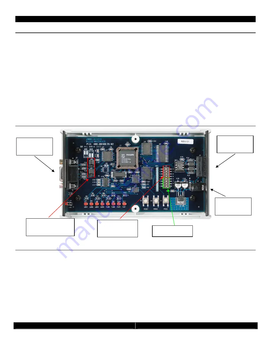
Detailed Diagram
Hardware Connection
There are two connections on the interface: a four wire phoenix connector for the Audioaccess keypad bus, and a nine
pin female for the serial connection to the device being controlled. The unit uses a straight through serial cable.
Depending on your particular device, you may need a turnaround adaptor.
Connection for RS-232 Control
The RS-232 Port can be configured as either Data Terminal Equipment (DTE) or Data Computer Equipment (DCE).
When configured as DTE (both jumpers at JP1 in the TOP position), pin 2 of the nine-pin D connector will be TxD, and
pin 3 will be RxD. When configured as DCE (both jumpers at JP1 in the BOTTOM position), pin 2 will be RxD and pin 3
will be TxD. When using the CATC to control a subsystem, consult the manufacturer’s manual for pin 2 and 3 use. The
pin outs must be opposite at the other end of the RS-232 connection. If pin 2 is TxD at the Interface Board, pin 2 at
the computer or subsystem end must be RxD. Set the CATC/2WSI JP1 jumper accordingly (refer to the chart on page
4).
Serial Port
(RS-232)
Audioaccess
Keypad Bus
DTE/DCE Jumpers
(JP1 &JP2)
Interface
Address
Device Type
Optional
Power (12V)


