


Parameter Settings
7
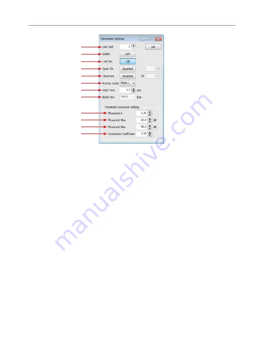
1.
Link Unit:
Select the number of the system unit; change the number and
click the “Set” button
2.
NOMA:
Set number of Open Microphones Attenuated (NOMA) On/Off
3.
Last Mic:
Select the Last Mic On/Off.
- In any of the modes of operation, the last microphone “ON” will
remain “ON” when talking ceases, to provide continuous room
ambience
4.
OpenCh:
Set the maximum number of channel openings from 1 to 16;
select “Disable”, the number of channel openings is not restricted
5.
Chairman:
When the channel set as the chairperson becomes open,
other channels are closed compulsorily
- The number means that Master’s channel 1 is “1” and channel
2 is “2”. Slave#1’s channel 1 is “9” and channel 2 is “10”….
Slave#15’s channel 8 is “128”
6.
Priority mode:
This mixer has two priority modes
The maximum gate open number limits the number of open channels
over the system
- Mode 1: The channel to which the priority was set also receives
restriction of the number of the maximum channels
- Mode 2: The channel to which the priority was set does not
receive restriction of the number of the maximum channels
7.
HoldTime:
Select the gate hold time 0.1 to 6.0 sec (0.1 sec stepping)
8.
Baudrate:
It is a baud rate of a mixer, and it can change the baud rate in
the online mode. A preset value is reflected after a mixer reboots; 38400,
57600, & 115200 bps
9.
Threshold K:
Auto threshold sensitivity. A higher value will make it more
difficult to trigger the gate open. Range is 1.00 to 3.00 (0.01 stepping)
10.
Threshold Max:
The maximum dB that will trigger a gate to open.
Reducing the possibility of transient sounds false triggering the gate.
Range is -80 to 0dB (0.1 stepping)
11.
Threshold Min:
The minimum dB that will trigger a gate to open.
Reducing the possibility of gates closing and interrupting active
dialogue. Range is -80 to 0dB (0.1 stepping)
12.
Correlation Coefficient:
This value adjust the calculations used to
determine if multiple channels are receiving the same source. A higher
value will make it more likely for multiple microphones to pass the same
source.
This value is factory set and in most cases should remain at the default
level of 0.50. Range is 0.01 to 1.00 (0.01 stepping)
Suggestions for using multiple microphones:
Proper adjustment of the
Threshold K for background noise and other non-intended audio will
ensure best operation of the auto-mixer.
Adjusting Threshold K:
This level should be set to the ambient noise of the
room (Computer fans, video projector fans, HVAC, etc.) so as not to
trigger the gain reduction.
With two people speaking into two microphones adjust the Threshold
K until the gain reduction activates and stays on during short pauses
in speech. This value should be increased in high ambient noise
applications.
Adjusting Threshold Maximum:
This controls false triggers of the automatic
gate regardless of the microphone channel gain setting. Setting this
level too low can cause transient sounds such as coughs or table
pounds to trigger a gate.
Adjusting Threshold Minimum:
will help control false triggers of the
automatic gate regardless of the microphone channel gain setting.
Setting this level too high can cause the gate to cut off words.
NOMA or Number of Open Microphones Attenuator utilizes audio thresholds
to manage a shared total gain. As more microphone channels are opened,
the gain of each channel is attenuated to achieve the same total output level
regardless of the amount of microphone gates open.
There are the limits of this automix method. When using more than 10
channels the NOMA setting may not be achievable in "Auto-Mode”.
Directions for using a manual mode and optimizing each channel individually
can be found on (P.19).
①
②
③
④
⑤
⑥
⑦
⑧
⑨
⑩
⑪
⑫


