Audio Technica AT-DMM828 Installation Instructions Manual Download Page 13

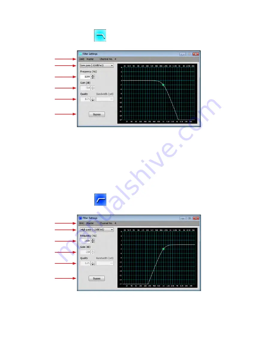
Double-click “Low Pass Filter” block, 

the following window will be displayed

Double-click “High Pass Filter” block, 

the following window will be displayed

Low Pass Filter Setting, -12 dB/oct

High Pass Filter Setting, -12 dB/oct

13

1.


Unit name and Channel No: 

The unit name and channel number to 

which this block is set will be displayed

2.


Filter Type:

 Click to change to other filter type

3. Frequency:

 Adjust the cut-off frequency from 20 Hz to 20 kHz (1 Hz 

stepping)

1.


Unit name and Channel No: 

The unit name and channel number to 

which this block is set will be displayed

2.


Filter Type:

 Click to change to other filter type

3. Frequency:

 Adjust the cut-off frequency from 20 Hz to 20 kHz (1 Hz 

stepping)

4. Gain:

 Fixed at -3 dB (non-adjustable)

5. Quality:

 Fixed at 0.71 (non-adjustable)

6. Bypass:

 When selected, it will bypass this filter

4. Gain:

 Fixed at -3 dB (non-adjustable)

5. Quality:

 Fixed at 0.71 (non-adjustable)

6. Bypass:

 When selected, it will bypass this filter

Summary of Contents for AT-DMM828

Page 1: ...AT DMM828 Digital Matrix Mixer Installation and Operation ...

Page 2: ...en moving the cart apparatus combination to avoid injury from tip over 13 Unplug this apparatus during lightning storms or when unused for long periods of time 14 Refer all servicing to qualified service personnel Servicing is required when the apparatus has been damaged in any way such as power supply cord or plug is damaged liquid has been spilled or objects have fallen into the apparatus the ap...

Page 3: ...ccur The link connectors are not compatible with LAN Each AT DMM828 includes two separate external control system interfaces Individual channel contact closures via DB25 connector and PC control via RS232 connector or USB The RS232 connector can also be used to connect an external control system e g Crestron or AMX using open disclosure communication protocol to control the mixer AT DMM828 Feature...

Page 4: ...cation protocols to configure internal mixer settings 3 Power ON indicator 4 Power Switch 5 Fan will automatically turn on when internal temperature exceeds 60 C 140 F 9 Link In Link Out connector RJ 45 Provides cascade connections of multiple mixers when more than eight microphones are used Use CAT6 cable Maximum length is 0 5m NOTE Use high quality CAT6 cable when linking mixers Signal degradati...

Page 5: ...is software requires Microsoft NET Framework 4 Client Profile If the computer does not have NET Framework 4 Client Profile installed the installation process will ask to install it during setup After installation process finishes it will ask to restart the computer Hardware Pentium processor running at 1 6 GHz or better 4 GB hard disk space recommended for application 1 GB RAM 9 pin RS232 Serial D...

Page 6: ...ging and dropping these blocks Refer to Customizing the DSP block Operations Blocks Descriptions 4 Preset maximum of 10 presets data can be saved in PC Yellow icon indicates it has already got preset data Right click either yellow or gray icon to save current setting Left click the yellow icon to load the preset data 5 Scale Can adjust the scale of the main block by sliding the button 6 Unit To se...

Page 7: ...ty of gates closing and interrupting active dialogue Range is 80 to 0dB 0 1 stepping 12 Correlation Coefficient This value adjust the calculations used to determine if multiple channels are receiving the same source A higher value will make it more likely for multiple microphones to pass the same source This value is factory set and in most cases should remain at the default level of 0 50 Range is...

Page 8: ...xternal control system Crestron or AMX is using open disclosure communications protocol 3 Serial Connect button The mixer is connected or disconnected to the PC via serial port 4 USB Connect button Select connect or disconnect to the PC using USB interface 5 Progressive Bar The progress of connection will be displayed Software Settings 1 Language Select the language that will display a Language av...

Page 9: ...ock which you want to add is chosen from an operation block area and it dragging and dropping on the line of a channel The number of the blocks which can be arranged to each channel has restriction The delay block can arrange only to output side 9 It can drop if a line changes to pink ...

Page 10: ... Frequency To select the center frequency Hz for the current band range is from 20 Hz to 20 kHz 1 Hz stepping 5 Gain To adjust the amount of boost or cut applied at the center frequency for the current band from 9 to 27 dB 0 1 dB stepping default at 0 dB 6 Quality Q or Quality factor selects the ratio of the center frequency divided by the bandwidth Q reflects an inverse relationship to the bandwi...

Page 11: ...cy To select the center frequency Hz for the current band range is from 20 Hz to 20 kHz 1 Hz stepping 5 Gain To adjust the amount of boost or cut applied at the center frequency for the current band from 9 to 27 dB 0 1 dB stepping default at 0 dB 6 Quality Q or Quality factor selects the ratio of the center frequency divided by the bandwidth Q reflects an inverse relationship to the bandwidth and ...

Page 12: ...Channel No The unit name and channel number to which this block is set will be displayed 2 Filter Type Click to change to other filter type 3 Frequency Adjust the center frequency from 20 Hz to 20 kHz 1 Hz stepping 4 Gain Fixed at 0 dB non adjustable 5 Quality Bandwidth Adjust the quality of the filter Q from 0 20 to 4 0 01 stepping default at 0 5 bandwidth oct from 4 74 to 0 36 0 01 stepping defa...

Page 13: ...ilter type 3 Frequency Adjust the cut off frequency from 20 Hz to 20 kHz 1 Hz stepping 1 Unit name and Channel No The unit name and channel number to which this block is set will be displayed 2 Filter Type Click to change to other filter type 3 Frequency Adjust the cut off frequency from 20 Hz to 20 kHz 1 Hz stepping 4 Gain Fixed at 3 dB non adjustable 5 Quality Fixed at 0 71 non adjustable 6 Bypa...

Page 14: ...lter type 3 Frequency Adjust the cut off frequency from 20 Hz to 20 kHz 1 Hz stepping 1 Unit name and Channel No The unit name and channel number to which this block is set will be displayed 2 Filter Type Click to change to other filter type 3 Frequency Adjust the cut off frequency from 20 Hz to 20 kHz 1 Hz stepping 4 Gain Fixed at 3 dB non adjustable 5 Quality Fixed at 0 71 non adjustable 6 Bypas...

Page 15: ...t name and channel number to which this block is set will be displayed 2 Filter Type Click to change to other filter type 3 Frequency Adjust the center frequency from 20 Hz to 20 kHz 1 Hz stepping 4 Gain Adjust the amount of cut or boost applied by the filter gain at 9 dB to 27 dB 0 1 dB stepping 5 Quality Adjust the quality of the band Q from 0 01 to 1 00 0 01 stepping 6 Bypass When selected it w...

Page 16: ... reduction is released once input signal falls below threshold Adjustable range is 0 to 2000 ms 1 ms stepping 1 Delay Time Determines the amount of delay Adjustable range is 0 to 300ms 1 ms stepping 2 Bypass button Disables the delay without changing settings 3 Ratio Determines the intensity of gain reduction Adjustable range is 1 1 to 20 1 0 1 stepping 4 Threshold Determines what input level will...

Page 17: ...color Input usage Light Blue color Output usage Unit 0 Master Unit Selection and its DSP Resource Usage Display Unit 1 Slave Unit 1 Selection and its DSP Resource Usage Display Unit and DSP Resource Monitor 17 ...

Page 18: ... Volume up down 5 Channel status output or Gate on off or Mute on off toggle or Volume up down 7 Channel status output or Gate on off or Mute on off toggle or Volume up down 9 Gate on off or Mute on off toggle or Volume up down Gate on off or Mute on off toggle or Volume up down Gate on off or Mute on off toggle or Volume up down Gate on off or Mute on off toggle or Volume up down VCA control or G...

Page 19: ...t either MIC or LINE LINE is already attenuated 30 dB Select the phantom power 48V ON OFF 9 Input source To select input source Audio input or White noise Pink noise Tone for channel calibration 10 Gate status The gate status of the channel is indicated 11 Force On OFF button To force the gate open or closed via software 12 Gate priority Set priority to each channel 13 Auto Target To select ON or ...

Page 20: ...lick on this button all input channels are disconnected to all output channels there is no output c Diagonal when click on this button each input channel is only connect to one respective output channel d Copy this button is for 2 or more units linking together when 2 or more units the Matrix Mixer Settings window will have additional matrix block that mark as Slave input block linking to Master o...

Page 21: ...2 Channel name To edit double click the name and edit 3 Volume Adjustable range is 80 to 0 dB 0 1 dB stepping 4 Mute button To mute each output channel Double click Outputs block the following window will be displayed When 2 or more units linking together the Main Window will display as follow ...

Page 22: ...ng dialog will be displayed when the internal composition of the mixer of the present then differs from the composition on PC application If YES is chosen a setup of PC application will be overwritten by the mixer The following dialog is displayed when only a parameter is different by the case where the composition of the present mixer is the same as that of PC application If YES is chosen a setup...

Page 23: ...input Frequency Response 20 to 20 000 Hz 3 dBr referenced at 1k Hz Equivalent Input Noise 117 8 dBu 120 dBV Gain at Max A weighted Rs 150 ohm input Maximum NOMA Attenuation 20 dB up to 100 mics on simultaneously Microphone Phantom Power 48V DC 2V DC Control Voltage Out 3 3V DC Latency 1ms Propagation delay from input to output Power Supply 100 240V AC 50 60 Hz 25W Operating Temperature 0 to 40 C 3...

Reviews: