


MAN - BBR2S - REV: Original | C. System Overview
9
Specimen Support
The bottom half of the load frame consists of an anvil with two metal supports designed for alignment of the
specimen. These specimen supports have a 3 mm contact radius and are fixed 102 mm apart from each other. They
are designed to align samples that are approximately 127.00 mm x 12.70 mm x 6.35 mm.
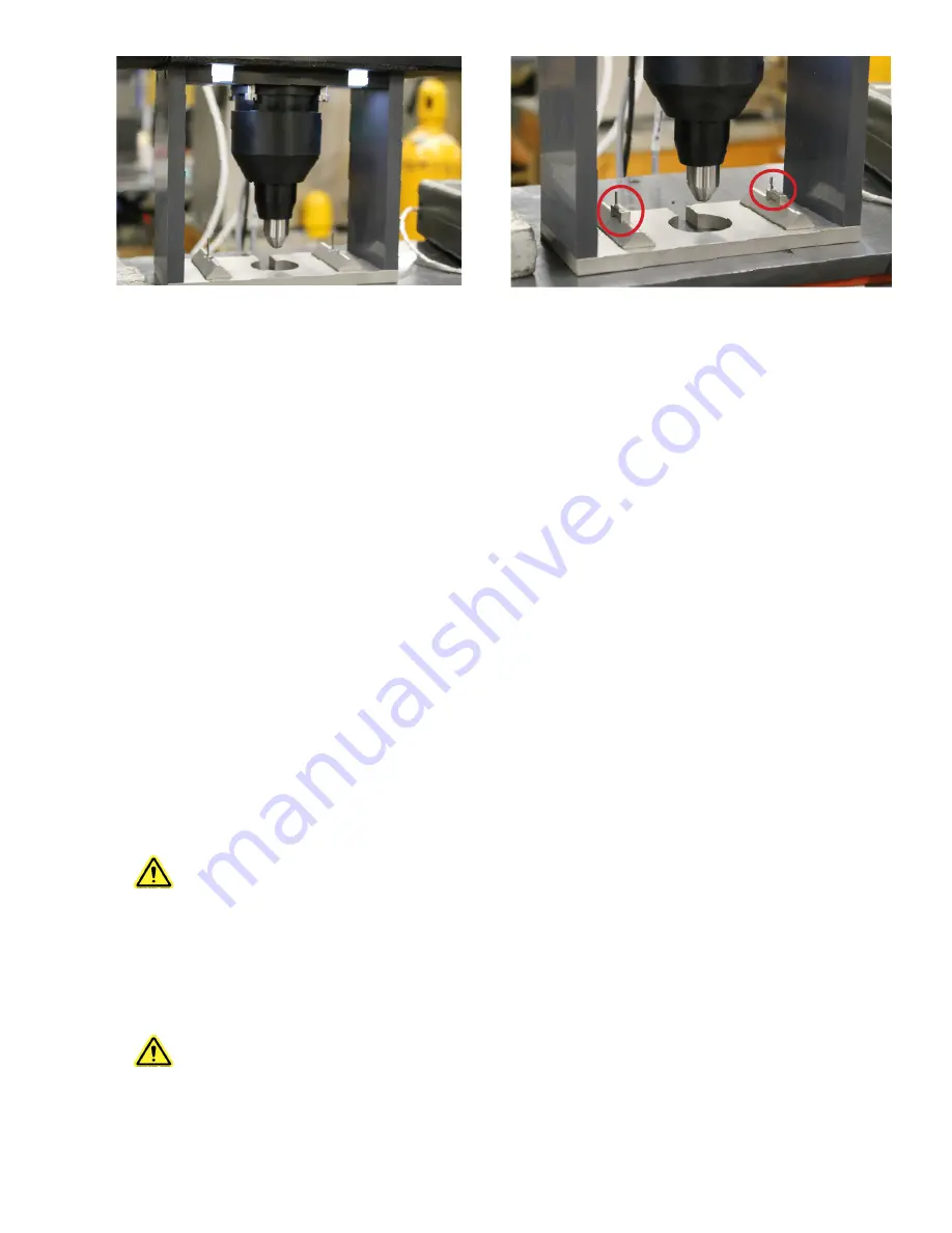
Resting on each of the anvil’s specimen supports are two anvil adapters (see Figure C.5). During crack sealant
testing these anvil adapters need to be removed by lifting STRAIGHT UP on the adapter and pulling it off of the
guide pin. The load frame should be removed from the bath and allowed to warm to room temperature before
removing the anvil adapters. The anvil adapters should be installed on the anvil supports for testing of any regular
asphalt binder samples.
The specimen supports and lower portion of the load frame are designed to be submerged in the constant-
temperature fluid bath during the test. The fluid in the bath provides a buoyant force that counterbalances the weight
of the specimen.
Linear Variable Differential Transformer (LVDT)
The LVDT is calibrated at between 0 and 6 mm and is mounted in the upper section of the load frame assembly. A
free-floating core rod is attached directly to the load shaft. It measures the displacement of the specimen as the test
load is applied.
CAUTION: Carefully place the calibration weights on the load cell’s weight pan. If the LVDT shaft
is bumped, it may become inaccurate or even permanently damaged.
Load Cell
The load cell is a precision strain gauge-type, with 500 gram (4903 mN) force capacity. It is constructed of stainless
steel to prevent corrosion or damage by the fluid during test procedures.
CAUTION: The load cell can be easily damaged, especially from side loading and excessive
torque. Use caution while handling the test frame when the loading shaft is attached. Remove
loading shaft before laying load frame on its side, especially before shipping.
Figure C.5 - Load Frame with Anvil Adapters
Figure C.4 - Load Frame without Anvil Adapters


