
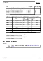


Reference
Description
1
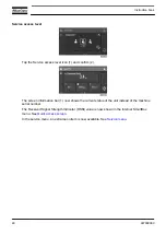
Right side view
2
Front view
3
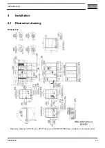
Motor cooling air outlet
4
Compressed air inlet
5
Motor cooling air inlet (only for option: separate air intake)
6
Motor cooling air inlet + compressor air inlet (for standard unit)
17
Automatic drain of intercooler G 1/2" (female)
18
Automatic drain of aftercooler G 1/2" (female)
20
Voltage supply: entrance for fixed speed compressors with supply ≤ 690 V
21
Voltage supply entrance:
• for fixed speed compressors with supply > 690 V
• VSD compressors (possibility 1)
• compressors with foot mounted motors
22
Top view
24
Compressed air outlet DN 80 PN 16 acc. DIN 2633 (Scale 1:5)
25
Compressed air outlet 3" 150 Lbs acc. ANSI B16.5 (Scale 1:5)
30
Compressed air outlet
36
Rear side view
37
Grating only for option: separate air intake
38
Voltage supply: entrance for VSD compressors (possibility 2)
41
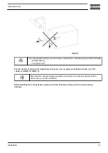
Opening for transportation
42
4 slotted holes to pull the compressor out of a container
43
Net mass of a standard compressor
44
Net mass of a compressor without a motor
51
Center of gravity Z 160-275
52
Center of gravity Z 250/315 VSD
53
Left side view (for hot air version)
54
Hot air version
55
Standard version
56
Water in/out DN 50 PN 16 acc. DIN 2633 (Scale 1:5)
57
1540 lb should be added in case of a high ambient temperature compressor or an
oversized motor or a motor with supply voltage > 690 V
58
Automatic drain of aftercooler G 1/2" (female) (not for hot air version)
Instruction book
50
AIF999999
Summary of Contents for ZR 200
Page 1: ...Instruction book AIF999999 ZR 200 ...
Page 2: ......
Page 61: ... CORRECT installation Instruction book AIF999999 59 ...
Page 108: ......
Page 109: ......