- 38 -
OPERATIONS OVERVIEW
It is possible to control the compressor locally with
the Control Box, remotely with the remote switch
inputs located on the back of the Control Box, or with
software running on a PC with a CAN interface (PC
Control Mode).
The way one ends up in each status can differ from
how the Control Box is controlled, but the function of
each status stays the same.
When reading this document, mind the difference
between a status and a procedure. A status is a state in
the Control Box's operation. A procedure is an action
executed by the Control Box.
Example: The Stopping procedure is executed in the
Stopping status, the Start Failure status and the
Shutdown status.
During operation
Regularly carry out following checks:
1. Ensure that the regulating valve (RV) is correctly
adjusted, i.e. starts decreasing the engine speed
when reaching the preset working pressure in the
receiver.
2. Check the air outlet temperature of the
compressor element.
3. Check the engine oil pressure, the coolant
temperature and display of control box.
4. Avoid the engine running out of fuel.
Nevertheless, if this happens, fill the fuel tank and
prime the fuel system to speed up starting (see
section
Specific start procedure
).
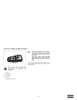
BATTERY SWITCH
The compressor is equipped with a battery switch.
When the compressor is not in use this switch must
always be switched off.
It is not allowed to use this switch as an emergency
switch or for stopping the compressor. It will cause
damage in the control unit when using this switch for
stopping.
Always first shut off the control unit and wait until the
display is dark before switching the battery switch
off.
When the engine is running, the air
outlet valves (ball valves) must always be
in a fully opened or fully closed position.
The doors must be closed during
operation and may be opened for short
periods for inspection and adjustments
only.
Please be aware that the (optional)
preheater unit is still “live” with the
battery switch switched off.
Summary of Contents for XAHS 447 Cd S3A APP
Page 2: ......
Page 24: ... 24 SH 03 ENGINE CIRCUIT 1 2 3 5 9 8 7 6 G 4 10 A B C D E F 9822 0963 49 ...
Page 25: ... 25 SH 04 CONTROL MODULE 1 2 3 5 9 8 7 6 4 10 A B C D 9822 0963 49 ...
Page 26: ... 26 SH 05 COMPRESSOR CIRCUIT 1 2 3 5 9 8 7 6 G 4 10 A B C D E F 9822 0963 49 ...
Page 27: ... 27 SH 06 OPTIONAL EQUIPMENT 1 2 3 5 9 8 7 6 G 4 10 A B C D E F 9822 0963 49 ...
Page 28: ... 28 SH 07 OPTIONAL EQUIPMENT 1 2 3 5 9 8 7 6 4 10 A B C D E 9822 0963 49 ...
Page 110: ... 110 Notes ...
Page 111: ......
Page 112: ......


