Manual, FT Sensor, ATI URCaps Software Installation and Setup for UR CB-Series
Document #9610-05-1036-07
Pinnacle Park • 1031 Goodworth Drive • Apex, NC 27539 • Tel: +1.919.772.0115 • Fax: +1.919.772.8259 •
15
4.
On the
Tool Center Point
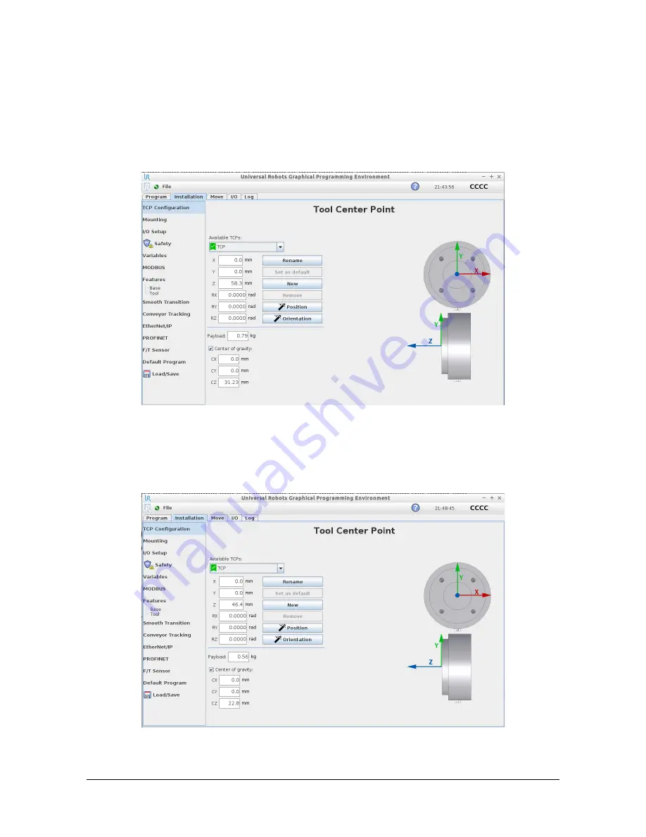
screen, type values in the fields, as applicable to the application. For
assistance in determining these values, refer to
Section 4.4—Determining the Tooling Mass and Offset
.
•
: The values entered in this figure are an example of a configuration that includes the
ATI mounting interface plate, the Axia sensor, and the tool interface plate. These values are from
. To these values, the user may need to add additional offset and payload to
account for the customer tooling.
Figure 4.9—TCP Screen (with tool interface plate)
•
: The values entered in this figure are an example of a configuration that includes the
ATI mounting interface plate and the Axia sensor. These values are from the
. To
these values, the user may need to add additional offset and payload to account for the customer
tooling.
Figure 4.10—TCP Screen (without tool interface plate)


