ATEN VanCryst VE8900 User Manual Download Page 32

VE8900 / VE8950 / VE8952 User Manual

20

Note:

1. The IR, RS-232, and USB signal transmissions are disabled by default. To 

enable the functions, go to 

System Settings

 > 

Receiver

 > 

IR/RS232

 or 

USB

 in VE Manager and select the signal source.

2. Each VE8952 transmitter can be controlled by a total of 4 USB touch 

screens installed to VE8952 receivers.

3. To receive HDMI audio on the VE8952 transmitter, make sure to 

configure the following in VE Manager:

Set the transmitter to receive HDMI audio: 
Go to 

System Settings

 > 

Transmitter

 > 

Audio In

 in VE Manager and 

change the setting to 

HDMI

.

To allow for 5.1 or 7.1 surround sound on a VE8952 receiver, do the 
following:

a) In VE Manager, go to 

System Settings

 > 

Transmitter

, access the 

configuration window for the corresponding transmitter, and then set 
EDID


to 

Manual

.

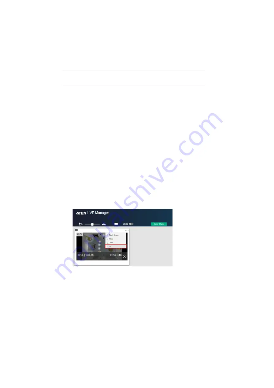
b) From the VE Manager’s preview area, click on the ... icon and select 

EDID to allow transmission of the receiver’s EDID to the transmitter.

Summary of Contents for VanCryst VE8900

Page 1: ...ATEN VanCryst VE8900 VE8950 VE8952 HDMI over IP Video Extender Series User Manual...

Page 2: ...to cause harmful interference in which case the user will be required to correct the interference at his own expense The device complies with Part 15 of the FCC Rules Operation is subject to the foll...

Page 3: ...r Manual iii HDMI Trademark Statement The terms HDMI HDMI High Definition Multimedia Interface and the HDMI Logo are trademarks or registered trademarks of HDMI Licensing Administrator Inc RoHS This p...

Page 4: ...s prove defective following their purchase the buyer and not the manufacturer its distributor or its dealer assumes the entire cost of all necessary servicing repair and any incidental or consequentia...

Page 5: ...about all ATEN products and how they can help you connect without limits visit ATEN on the Web or contact an ATEN Authorized Reseller Visit ATEN on the Web for a list of locations and telephone numbe...

Page 6: ...your dealer VE8900T 1 VE8900 HDMI over IP Transmitter 1 RS 232 terminal block 1 5V power adapter 4 foot pads 1 user instructions VE8900R 1 VE8900 HDMI over IP Receiver 1 RS 232 terminal block 1 5V po...

Page 7: ...5V power adapter 4 foot pads 1 user instructions VE8952R 1 VE8952 4K HDMI over IP Receiver with PoE 1 RS 232 terminal block 1 5V power adapter 4 foot pads 1 user instructions VE8952T 1 VE8952 4K HDMI...

Page 8: ...p View 12 VE8900R VE8950R VE8952R Top View 13 Mounting the VE8900 VE8950 VE8952 Device 14 Wall Mount 14 Rack Mount 14 Connecting VE8900 VE8950 15 Connecting VE8952 18 3 Panel Operation Overview 21 Sta...

Page 9: ...ration 59 Maintenance 61 Upgrading VE8900 VE8950 VE8952 Device Firmware 61 Synchronizing All Devices 62 Backing Up VE8900 VE8950 VE8952 Device Settings 62 Restoring VE8900 VE8950 VE8952 Device Setting...

Page 10: ...of a Transmitter 85 Examples 85 Setting the Fast Switch Output Resolution of a Receiver 86 Examples 86 Applying Profile via the Profile Name or ID 87 Example 87 7 Mobile Control App Overview 89 Requi...

Page 11: ...he VE Manager s main screen and step by step instructions of creating and editing display layouts Chapter 5 System Settings provides information on the general settings and how to back up restore and...

Page 12: ...If keys need to be chorded they appear together in the same bracket with a plus sign between them Ctrl Alt 1 Numbered lists represent procedures with sequential steps Bullet lists provide information...

Page 13: ...l digital signage solution with the following features and advantages Limitless scalability and flexibility No complicated IP setup No additional server PCs or software required Go further for less wi...

Page 14: ...High Quality for users to choose depending on practical usage Power over Ethernet Support Locate VE8952 anywhere without having to install additional power cabling and outlets Note Only VE8952 support...

Page 15: ...E8952 supports PoE and can be installed in combination with PoE Ethernet switches to reduce power cabling and additional power outlets For more information about choosing the Ethernet switch or bandwi...

Page 16: ...s to arrange the profile by grouping individual receiver or video wall Multiple profiles can be arranged to play in any order over a selected period of time No Complicated IP Setup Simple configuratio...

Page 17: ...s Please contact ATEN representatives for more details For Daisy Chain installation setup for VE8952 units only the first level of VE8952 supports PoE powering function All the other VE8952 units inst...

Page 18: ...VE8900R VE8950R VE8952R audio stream can be extracted from the HDMI stream and delivered as a separate audio signal Multiple Control Channels Multiple control methods the system can be managed via Eth...

Page 19: ...ct the VE8900 VE8950 VE8952 devices to sources displays network and other hardware devices as required For more information see the installation diagrams on Connecting VE8900 VE8950 page 15 and Connec...

Page 20: ...VE8900 VE8950 VE8952 User Manual 8 This Page Intentionally Left Blank...

Page 21: ...bi directional IR port Connects to an IR receiver transmitter to allow for configuration using a remote control 4 RS 232 serial port Connects to a computer for serial control 5 USB Type B port Connect...

Page 22: ...ck Connects to the DC power adapter to provide power to the unit No Component Function 1 USB Type A ports Connects to virtual media or a USB peripheral device 2 RS 232 serial port Connects to a serial...

Page 23: ...with PoE Connects the unit to LAN with a network cable Note Only VE8952 supports PoE function and VE8900 VE8950 does not 2 LAN 2 port Connects to another VE8900R VE8950R with a network cable in a dai...

Page 24: ...prev next buttons Assign ID numbers on VE8900 VE8950 devices Assign the source video transmitter for the receiver 3 link LED Lights orange to indicate the LAN port 1 is connected to an Ethernet switc...

Page 25: ...VE8900 VE8950 devices Assign the source video transmitter for the receiver 4 Tx Rx switch button Press to switch control between a receiver and its corresponding transmitter 5 HDMI out LED Lights oran...

Page 26: ...VE8952 Device Wall Mount Secure or hang the VE8900 VE8950 VE8952 device to the wall using the built in brackets Rack Mount Use the VE RMK1U Rack Mount Kit to rack mount the VE8900 VE8950 VE8952 For mo...

Page 27: ...ction or signal transmission see Status LEDs page 21 For a list of compatible ATEN products visit the VE8900 VE8950 product web page at www aten com Serial Device Remote HDMI Device HDMI Source Device...

Page 28: ...oyment connect the LAN 1 ports of your VE8900T VE8950T and VE8900R VE8950R to the same Ethernet switch with RJ 45 cables 4 Plug the power adapter into the power jack on the VE8900T VE8950T and VE8900R...

Page 29: ...VE8900 VE8950 transmitter make sure to configure the following in VE Manager Set the transmitter to receive HDMI audio Go to System Settings Transmitter Audio In in VE Manager and change the setting t...

Page 30: ...r signal transmission see Status LEDs page 21 For a list of compatible ATEN products visit the VE8952 product web page at www aten com VE8952R VE8952T 1 2 3a 4 4 5 6 6 7 7 5 7 3b 3b Remote HDMI Device...

Page 31: ...ugh an Ethernet cable if the unit is connected to a PoE supported Ethernet switch Alternatively plug the power adapters into the power jacks on the VE8952T and VE8952R Note When power supply is availa...

Page 32: ...the VE8952 transmitter make sure to configure the following in VE Manager Set the transmitter to receive HDMI audio Go to System Settings Transmitter Audio In in VE Manager and change the setting to H...

Page 33: ...ceivers LED Indication Description power Lights green The device is powered on Off Power is off link Lights orange LAN is connected Off LAN is not connected HDMI out Lights orange The video output is...

Page 34: ...50 Note The unit used in the diagram above is VE8900 VE8950 the panel control for VE8952 is identical No Name Description 1 Tx Rx LEDs Lights to indicate whether the displayed ID number is of Tx or Rx...

Page 35: ...digits letter A b c d E and F are used to replace the first two digits A 10 A00 A99 to display ID number 1000 1099 b 11 b00 b99 to display ID number 1100 1199 c 12 c00 c99 to display ID number 1200 1...

Page 36: ...VE8952R devices 2 For a matrix setup assign an ID number to each of your VE8900T VE8950T VE8952T devices a On a VE8900T VE8950T VE8952T device use the prev and next buttons to assign an ID number to...

Page 37: ...sed through a web browser this utility provides a central platform that allows you to do the following Feature Details Configure transmitter and receiver settings See Transmitter Settings page 55 and...

Page 38: ...VE8950R VE8952R 4 Scroll down the page to find IP Installer zip file under Software Drivers Click the file to download 5 Unzip and execute the downloaded IP Installer The Network Device IP Installer s...

Page 39: ...Download materials for other products and press OK 3 Scroll down the page and click either VE8900T VE8900R or VE8952R 4 Scroll down the page to find VE Browser zip file under Software Drivers Click th...

Page 40: ...e scroll bar on the right to scroll through the list Use the icon top right hand corner to determine way the list is ordered Click the icon to toggle between By Name By Id and By IP and the selected w...

Page 41: ...go directly into VE Manager login page using the Find My VE Extension To do so follow the steps below 1 In the Windows Start menu click to select Find My VE 2 In the Find My VE window click the bar of...

Page 42: ...VE8900 VE8950 VE8952 User Manual 30 Please refer to Logging In and Configuring VE Manager on page 31 for information about logging in...

Page 43: ...Level and type password for the Password field This screen appears upon first login Note If you are the administrator and are logging in for the first time use the default Password password For secur...

Page 44: ...rs The setup wizard lists the VE8900 VE8950 VE8952 transmitters and receivers found in the network 5 To configure device IP addresses select the devices from the list and then click Next This screen a...

Page 45: ...id IP address ranges c Click Refresh to start assigning IP addresses d When the assignment is complete VE Manager displays the assigned IP addresses 8 To re assign device IDs click and type a new ID f...

Page 46: ...ividual video receivers and daisy chain setups For details about creating video wall templates see Creating a Video Wall Layout page 40 For details about controls in a preview see Editing a Preview pa...

Page 47: ...efresh Update the Daisy Chain Status 6 Auto Apply Check to enable auto apply where all the settings are automatically applied to the devices 7 Profile Schedule Click to enter profile scheduling page F...

Page 48: ...VE Manager 1 On the main screen identify the source you wish to be assigned in the Source List and the preview video walls receivers 2 Select and drag the source to the preview video walls receivers...

Page 49: ...sources there Follow the steps below 1 From the main screen click and then click the Receiver tab The managed VE8900 VE8950 VE8952 receivers appear 2 Assign a source for each of the VE8900 VE8950 VE8...

Page 50: ...n This window appears d Click the Connected Tx drop down arrow and select a Tx source e Repeat steps 2 a to 2 d to assign sources for each of the receivers f To reboot the VE8900 VE8950 VE8952 click t...

Page 51: ...Wall Layout page 40 2 From the VE Manager s main screen drag and drop input sources from the Source List onto the created video wall layout In the following example the display source T002 is assigne...

Page 52: ...Displays Define the following parameters Horizontal and Vertical Click the drop down boxes to select the number of displays for your video wall Click Refresh to show a preview of your configuration Di...

Page 53: ...mized Select this option to create a customized display Click New layout in the list to rename this template Click and hold the slider bar to enlarge or reduce the size of preview windows Use this but...

Page 54: ...template is created Editing a Video Wall Layout To edit a video wall layout from the VE Manager s main screen click the top right corner of the layout you wish to edit and then select Edit For more de...

Page 55: ...e assigned receiver 3 Configuration Menu Click the top right corner to access the following controls Blank Disables the display on this video wall Mute Disables audio transmission to this video wall O...

Page 56: ...gs you can save it as a profile You can create different profiles and apply them manually or you can set up profile schedules for switching video display at different times of a day week or month Crea...

Page 57: ...Name Enter a profile name Receivers Video Walls Select the receivers video walls you wish to be in this profile by checking the orange box Alternatively you can select all receivers video walls by ch...

Page 58: ...k the green arrow for a drop down menu of edit delete and disconnect options Edit To edit the profile click the Edit option Profile Name Edit the profile name Receivers Video Walls Select de select th...

Page 59: ...ile click the Delete option The system will ask if you would like to delete this profile Click OK to proceed or click CANCEL to cancel Disconnect To disconnect the current profile from the video wall...

Page 60: ...receiver video wall selected in the profile will be displayed If the current video receivers video walls show yellow background it indicates that the video settings have not be applied If the backgro...

Page 61: ...the profile schedule icon on the top right hand corner An example of profile schedule screen with nothing planned is shown below On this page you can select to show current schedule of either 1 DAY 3...

Page 62: ...s option to run this schedule only once Daily Select this option to run this schedule everyday Weekly Select this option to run this schedule every week You can also select which days you wish the sch...

Page 63: ...Chapter 4 Management 51...

Page 64: ...devices using by clicking from the main screen and then the Transmitter or Receiver tab The status for a VE8900 VE8950 VE8952 device is indicated with a colored circle See the table below for status...

Page 65: ...neral tab Date and time Click and type the desired information and click Set to save the settings Sync with computer time If you wish to synchronize the time with the computer s time check the checkbo...

Page 66: ...s To unlock the panel of a single VE8900 VE8950 VE8952 device press and hold the Down button on the top panel for 3 seconds Installation Wizard Click on the top right corner to open up the installatio...

Page 67: ...mitter settings follow the steps below 1 From the main screen click and then click the Transmitter tab The managed VE8900 VE8950 VE8952 transmitters appear 2 Move the cursor to a transmitter you wish...

Page 68: ...device Audio In Select your audio signal type EDID After receiving EDID information from the connected display the VE8900T VE8950T VE8952T analyzes this information and sets up the input source Selec...

Page 69: ...s follow the steps below 1 From the main screen click and then click the Receiver tab The managed VE8900 VE8950 VE8952 receivers appear 2 Move the cursor to a receiver you wish to configure A green ar...

Page 70: ...ath Select this option to receive IR RS 232 signals from the transmitter Connected Tx where the receiver obtains its video source Manual Use this setting to select a different source for obtaining IR...

Page 71: ...st a particular setting for a group of devices do the following 1 Click Quick Configuration for a drop down menu 2 Select a setting you wish to configure The available options for the drop down menu w...

Page 72: ...n the list check Select All on the top left hand corner and click NEXT The Quick Configure window will appear and you can see each device s current status A drop down menu is available at the bottom o...

Page 73: ...s below 1 From the main screen click and click the Maintenance tab This screen appears The Firmware Upgrade section lists the detected transmitter and receiver devices and their firmware versions 2 Cl...

Page 74: ...system to recognize the added replaced device Backing Up VE8900 VE8950 VE8952 Device Settings You can export transmitter and receiver layouts for backup or migration purposes 1 From the main screen c...

Page 75: ...settings file 3 Click Restore to start overwriting the settings to the VE Manager A confirmation message appears when the backup is complete Recovery Mode There are four conditions that require recove...

Page 76: ...efault passwords and privileges are detailed in the table below To change the default password click from the main screen and then click the Account tab Account Level Default Password Privileges Admin...

Page 77: ...and configure the VE8900 VE8950 VE8952 devices using telnet TCP or RS 232 commands from a PC or an ATEN Control Box Before You Start Make sure you have installed a PC or an ATEN Control Box to the Et...

Page 78: ...for your PC do the following to connect to your deployment Telnet connections In the command prompt type the IP address of any VE8900 VE8950 VE8952 receiver in your setup and use port 23 For example...

Page 79: ...execute For information on command syntax see Commands page 68 4 Press Enter to execute the command 5 When the command is successfully executed the system returns a confirmation message 6 To end the s...

Page 80: ...ave two or more controls the order of these controls among themselves does not affect the result of the operation For example both of the following commands execute the same task command name control...

Page 81: ...w i1 o5 on To stop source transmission from a VE8900 transmitter with the IP address of 10 0 70 43 to a VE8900 receiver with the ID of 3 type sw i10 0 70 43 o3 off Control Description i port Indicates...

Page 82: ...0 transmitter with the ID of 1 to a VE8950 receiver with an ID of 6 type sw i1 usb o6 Control Description i port Indicates the device ID of the input source VE8900 VE8950 VE8952 transmitter device o p...

Page 83: ...video USB RS 232 and IR paths for a VE8900 receiver with an ID of 4 type sw o4 all off Control Description o port Indicates the device ID of the output VE8900 VE8950 VE8952 receiver device all Stands...

Page 84: ...remote control To enable or disable this function type the command in this format echo on off R N Control Description on Sends an alert in the command prompt window to inform port switching configurat...

Page 85: ...tem information of all VE8900 VE8950 VE8952 receivers in the environment including the device IDs MAC ID IP addresses firmware versions and device names tx Lists the system information of all VE8900 V...

Page 86: ...ID of any VE8900 VE8950 VE8952 receiver used in the target video wall To look up video wall IDs use the list command For details see Looking Up System Settings page 73 Example l layout_ID Indicates th...

Page 87: ...you wish display the specified source i port Note If the specified layout contains a 4 displays two of which are merged you will need 3 pairs of o port i port to indicate the source to be displayed o...

Page 88: ...rol Description o port Indicates the device ID MAC ID or the IP address of the output VE8900 VE8950 VE8952 receiver device you wish to mute Use an asterisk to mute all VE8900 VE8950 VE8952 receivers i...

Page 89: ...IP address of the output VE8900 VE8950 VE8952 receiver device you wish to disable the video output from or use to disable video output from all VE8900 VE8950 VE8952 receivers in the setup video_wall_...

Page 90: ...all ID 0 type osd f0 off Control Description o port Indicates the device ID MAC ID or the IP address of the output VE8900 VE8950 VE8952 receiver device for which you wish to display the OSD video_wall...

Page 91: ...Use an asterisk to target all VE8900 VE8950 VE8952 transmitters in the environment EDID_mode Indicates the EDID mode you wish to set to the specified VE8900 VE8950 VE8952 transmitter Valid inputs incl...

Page 92: ...trol Description a port Indicates the MAC ID or the IP address of the target VE8900 VE8950 VE8952 transmitter or receiver i port Indicates the device ID MAC ID or the IP address of the target input so...

Page 93: ...r the IP address of the target VE8900 VE8950 VE8952 transmitter or receiver i port Indicates the device ID MAC ID or the IP address of the target input source VE8900 VE8950 VE8952 transmitter device U...

Page 94: ...952 receiver with the IP address of 10 0 80 66 type read o10 0 80 66 To look up the connection status of VE8900 VE8950 VE8952 transmitters to VE8900 VE8950 VE8952 receivers in the environment type rea...

Page 95: ...analog audio source of a VE8900 transmitter with the IP address of 10 0 90 19 type audiomap a10 0 90 19 analog Control Description a port Indicates the MAC ID or the IP address of the target VE8900 VE...

Page 96: ...e o5 Control Description a port Indicates the MAC ID or the IP address of the target VE8900 VE8950 VE8952 transmitter or receiver Use an asterisk to target all VE8900 VE8950 VE8952 transmitters and re...

Page 97: ...of a VE8900 transmitter with the ID of 3 type hdcp i3 on Control Description a port Indicates the MAC ID or the IP address of the target VE8900 VE8950 VE8952 transmitter i port Indicates the device I...

Page 98: ...10 0 90 56 type fastswitch a10 0 90 56 off Control Description a port Indicates the MAC ID or the IP address of the target VE8900 VE8950 VE8952 receiver o port Indicates the device ID MAC ID or the IP...

Page 99: ...ts profile name or ID type the command in this format profile f profileid r n Example To apply a pre configured profile with the profile name of test123 type profile ftest123 Control Description f pro...

Page 100: ...VE8900 VE8950 VE8952 User Manual 88 This Page Intentionally Left Blank...

Page 101: ...ng and Configuring the App 1 Install the VE8900 VE8950 VE8952 Mobile Control App on a mobile device a From the mobile device tap the App Store or Google Play icon b In the search box type VE8900 mobil...

Page 102: ...f the functions on each tab Note If you are the administrator and are logging in for the first time use the default username and password admin password For security purposes the system will prompt yo...

Page 103: ...ave installed new display devices or made changes to the settings tap Sync to refresh Switching a Source 1 In the VE8950 Mobile Control App tap the Live icon 2 Tap any area on the receiver or the vide...

Page 104: ...VE8952 User Manual 92 3 Tap the source you wish to change to Currently used source is indicated with a red box and the new source is in green 4 Tap the tick icon on the selected source to apply the c...

Page 105: ...Control App 93 Switching Multiple Sources and Displays 1 In the VE8950 Mobile Control App tap the Switching icon This screen appears 2 Select a source a Tap Tx to add a source A list of available tra...

Page 106: ...lection c Tap Done to add the device to the Tx List 3 Select one or more displays Tap Rx to add one or more Rx devices Selected Rx devices are indicated in green When you tap a device that is grouped...

Page 107: ...ou have finished configuring the Tx and Rx lists should contain the devices you selected For example 4 To edit your selection tap to return to the Tx or Rx list 5 Tap Apply to complete the configurati...

Page 108: ...n the VE8950 Mobile Control App tap the Live icon 2 Find the video wall or the display that you wish to configure and then tap the Edit icon This page appears 3 Tap Operation Mode to change the displa...

Page 109: ...ow to apply a profile For details on creating or editing a profile see Creating a Profile page 44 and Edit Delete and Disconnect Profile page 46 1 In the VE8950 Mobile Control App tap the Live icon 2...

Page 110: ...or the day appear 2 To change the display date tap on the top left corner and select a date from the pop up calendar 3 Tap on the time zone that contains the profile you want to configure All the prof...

Page 111: ...follow the on screen instructions to configure its Start Date End Date and Repeat mode Note Keep the Start Date and End Date within 24 hours If you need to schedule a profile for more than 24 hours pe...

Page 112: ...configure the Video Quality and Pop up OSD setting Firmware Upgrades Shows the firmware versions for the VE8900 VE8950 VE8952 Tx and Rx devices and indicate if a newer firmware is available for each T...

Page 113: ...ice should not be placed in a built in enclosure unless adequate ventilation has been provided Never spill liquid of any kind on the device Unplug the device from the wall outlet before cleaning Do no...

Page 114: ...Liquid has been spilled into the device The device has been exposed to rain or water The device has been dropped or the cabinet has been damaged The device exhibits a distinct change in performance i...

Page 115: ...r out of a rack the slide rails can pinch your fingers After a device is inserted into the rack carefully extend the rail into a locking position and then slide the device into the rack Do not overloa...

Page 116: ...ady beforehand Product model number serial number and date of purchase Your computer configuration including operating system revision level expansion cards and software Any error messages displayed a...

Page 117: ...x 2160 3840 x 2160 30Hz 4 4 4 Audio Output 1 x HDMI Type A Female Black 1 x Mini Stereo Jack Female Green Connectors Unit to Unit 2 x RJ 45 Female Power 1 x DC Jack Black with locking 1 x DC Jack Blac...

Page 118: ...0 x 80 RH Non Condensing Physical Properties Housing Metal Weight 0 49 kg 1 08 lb 0 68 kg 1 50 lb Dimensions L x W x H with Bracket 14 02 x 12 30 x 3 06 cm 5 52 x 4 84 x 1 20 in 17 02 x 14 69 x 3 00 c...

Page 119: ...4 2 0 4096 x 2160 3840 x 2160 30Hz 4 4 4 Audio Input 1 x HDMI Type A Female Black 1 x Mini Stereo Jack Female Green Connectors Unit to Unit 1 x RJ 45 Female Power 1 x DC Jack Black with locking 1 x D...

Page 120: ...0 x 80 RH Non Condensing Physical Properties Housing Metal Weight 0 50 kg 1 10 lb 0 67 kg 1 48 lb Dimensions L x W x H with Bracket 14 02 x 12 30 x 3 06 cm 5 52 x 4 84 x 1 20 in 17 02 x 14 69 x 3 00 c...

Page 121: ...109 Supported Browsers Please see the table below for supported web browsers and the versions Web Browser Supported Versions Google Chrome 60 0 3112 or later Mozilla Firefox 54 0 1 or later Opera 46...

Page 122: ...on have the option to 1 repair said product with new or repaired components or 2 replace the entire product with an identical product or with a similar product which fulfills the same function as the...

Reviews: