


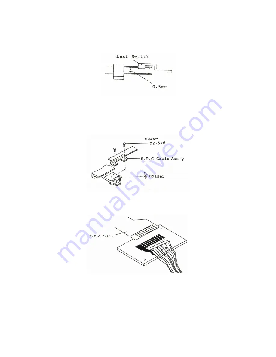
2) Insert the paper to print out and check the gap
of the contact points of the Leaf Switch shall be
more than 0.5mm (measured with thickness gauge).
6. Replacement of F.P.C Ass'y
1) Remove the Flexible Cable of the Printer Head from
F.P.C cable Ass'y on Printer Head Holder.
2) Remove two M2.5x6 screws, and take out the F.P.C Cable
Ass'y from the Printer Head Holder.
3) Resolder the F.P.C Cable from the Connection P.C.B
F.P.C Cable
4) In case assembling, Do reverse of 3), 2), 1)
-44-
Summary of Contents for XMM801
Page 1: ......
Page 2: ...SERVICE MANUAL PERIPHERAL PRINTER XMM 801...
Page 6: ...Figure 3 Internal Structure 2...
Page 11: ...8 XMM801 Timing chart at Power ON Figure 12 Timing Chart 7...
Page 14: ...Figure 18 Circuit Diagram 10...
Page 15: ...Figure 19 Parts Layout and Pattern Schematic 11...
Page 16: ...Figure 19 cont Parts Layout and Pattern Schematic 11a...
Page 18: ...5 Electric Circuit for Printer Mechanism Figure 22 Connection Diagram 13...
Page 20: ...Figure 23 TROUBLE 1 PRINTER IS TOTALLY OUT OF WORK 15...
Page 21: ...Figure 24 TROUBLE 2 INCORRECT FUNCTION OF PRINTER MECHANISM 16...
Page 23: ...Figure 26 TROUBLE 4 FEED MOTOR IS NOT WORKING 18...
Page 39: ...34...
Page 40: ...35...
Page 41: ...36...