


• Check the three screws which fix Ribbon Gear
Ass'y on the chassis are slightly loosed.
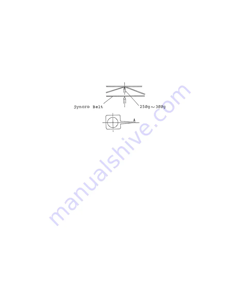
• Push the middle of Synchronous Belt by Tension
gauge until slightly touching to other side of
Synchronous Belt, and check the tensions within
250g ~ 300g.
If not within the specified value, adjust the
location of Ribbon Gear Ass'y.
• Then, fix the three screws firmly.
3. Replacement and Adjustment of Carriage Motor Ass'y
3-1 Disassemble and Assemble
1) Remove the Connector CON 6, 8 (Connected from
Carriage Motor) from Main P.C.B Assembly.
2) Take out the three M3x6 screws which fix the
Carriage Motor Aassembly.
-40-
Summary of Contents for XMM801
Page 1: ......
Page 2: ...SERVICE MANUAL PERIPHERAL PRINTER XMM 801...
Page 6: ...Figure 3 Internal Structure 2...
Page 11: ...8 XMM801 Timing chart at Power ON Figure 12 Timing Chart 7...
Page 14: ...Figure 18 Circuit Diagram 10...
Page 15: ...Figure 19 Parts Layout and Pattern Schematic 11...
Page 16: ...Figure 19 cont Parts Layout and Pattern Schematic 11a...
Page 18: ...5 Electric Circuit for Printer Mechanism Figure 22 Connection Diagram 13...
Page 20: ...Figure 23 TROUBLE 1 PRINTER IS TOTALLY OUT OF WORK 15...
Page 21: ...Figure 24 TROUBLE 2 INCORRECT FUNCTION OF PRINTER MECHANISM 16...
Page 23: ...Figure 26 TROUBLE 4 FEED MOTOR IS NOT WORKING 18...
Page 39: ...34...
Page 40: ...35...
Page 41: ...36...