


5
DMP8800
English
20. RS232 Interface
Standard RS232 interface is provided to facilitate third-
party external control system operation of the DMP8800�
21. Word Clock
Word clock connections essentially help keep your gear in
sync� If two digital audio devices have different sampling
rates, there could be sample skipping, jittering, delays
and other unwanted anomalies in your digital afudio�
Word clock synchronization is imperative to keep them at
the same sampling rates and ensure this does not occur�
When, for example, using several AES/EBU devices in a
chain, a master word clock connected to each device will
help them become perfectly synchronized�
22. AES/EBU Connectors
These connectors are for digital devices with AES/EBU
inputs and outputs�
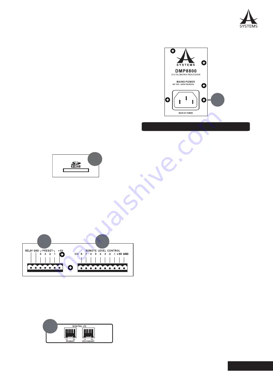
23. SD Card Slot
Insert an SD card into this slot to integrate MP3 files into
your mix�
24. Preset Recall
These connectors are compatible with the Asystems
RM-4 remote controls� See the Remote Control section
of this manual for wiring instructions�
25 Remote Level Control
These euroblock connections can be wired to connect the
Asystems RM-2VR remote level controls� Each RM-2VR
allows for two channels to have their levels controlled�
26. Digital I/O Expansion Card Slot
For installing Asystems DT22/DT44/DT88 Dante
Networking card to enable DMP devices as a networking
portal to other audio devices�
27. AC Power Connector
This is for a standard IEC power cable�
DMP MATRIX SOFTWARE
Firmware
Before beginning, it’s a good idea to ensure you’ve
installed the latest firmware. The latest firmware can
always be found on www�asystems-sys�com� Place
the firmware update file onto a FAT-32 formatted USB
memory stick and connect it to one of the DMP8800’s
rear-panel USB slots� Open the DMP8800’s internal
software then enter the Utility menu� At the bottom of this
menu is the firmware update function. Push the “Update”
button to perform a firmware update.
Connection
For a connection to be established between the Asystems
remote software and the DMP8800, first both need to be
connected to the same local area network or be ‘online’
(ie. on the internet). Opening the Network settings menu
in the DMP8800’s onboard software will allow users to
view or edit properties such as IP address� On a local
area network, this will be shown 192.168.x.x (where x
is dependent on your network). After setting the unit’s
IP address, this can be entered into the Aystems remote
software’s setup section to locate the DMP8800� A user
name and password can be set to protect the unit from
unauthorized control�
Metering
The front panel of the DMP8800 offers 8 level meters
for monitoring input and output signals� These meters
also include clip indicators to show when signals are so
excessive as to clip the signal� For additional metering
of individual signals and mixes, the matrix pages of the
DMP8800 software can be consulted�
23
24
25
26
27
30W
Summary of Contents for DMP8800
Page 1: ...User s Manual Manual del Usuario Digital Matrix Processor DMP8800 ...
Page 23: ...1 DMP8800 Español ...
Page 42: ......
Page 43: ......
Page 44: ...www asystems sys com ...


