ASMV-160
BETRIEBSANLEITUNG | OPERATING MANUAL
Technische Änderungen vorbehalten. Alle Angaben ohne Gewähr. Alle Rechte liegen bei der ASUTEC GmbH.
Subject to technical modifications. No responsibility is accepted for the accuracy of this information. All rights are reserved by ASUTEC GmbH.
Document nr. 85000061 – Version A – 2017/03/03
WWW.ASUTEC.EU
| 10
10
10
10
5.4
MONTAGE INDUKTIVE SENSOREN
5.4
MOUNTING OF INDUCTIVE
SENSORS
Für die Montage der induktiven Sensoren
werden Klemmhalter M16x1 in kurzer
Ausführung verwendet.
In diese Klemmhalter werden die Sensoren
M12x1 bündig eingebaut. Verwenden Sie
Sensoren mit 4 mm Bemessungsschaltabstand.
Die Gewindebohrungen am Gerät sind im
Anlieferungs-zustand mit Verschlussstopfen
verschlossen. Für die Montage der Klemmhalter
müssen diese Verschlusstopfen entfernt werden.
For mounting the inductive sensors, mounting
clamps M16x1 in short version are used.
In these mounting clamps the sensors can be
flush mountend. Use sensors with a rated
operating distance of 4 mm.
The tapped holes on the device are sealed with
the plug when delivered. For mounting the tool
holder these sealing plugs must be removed.
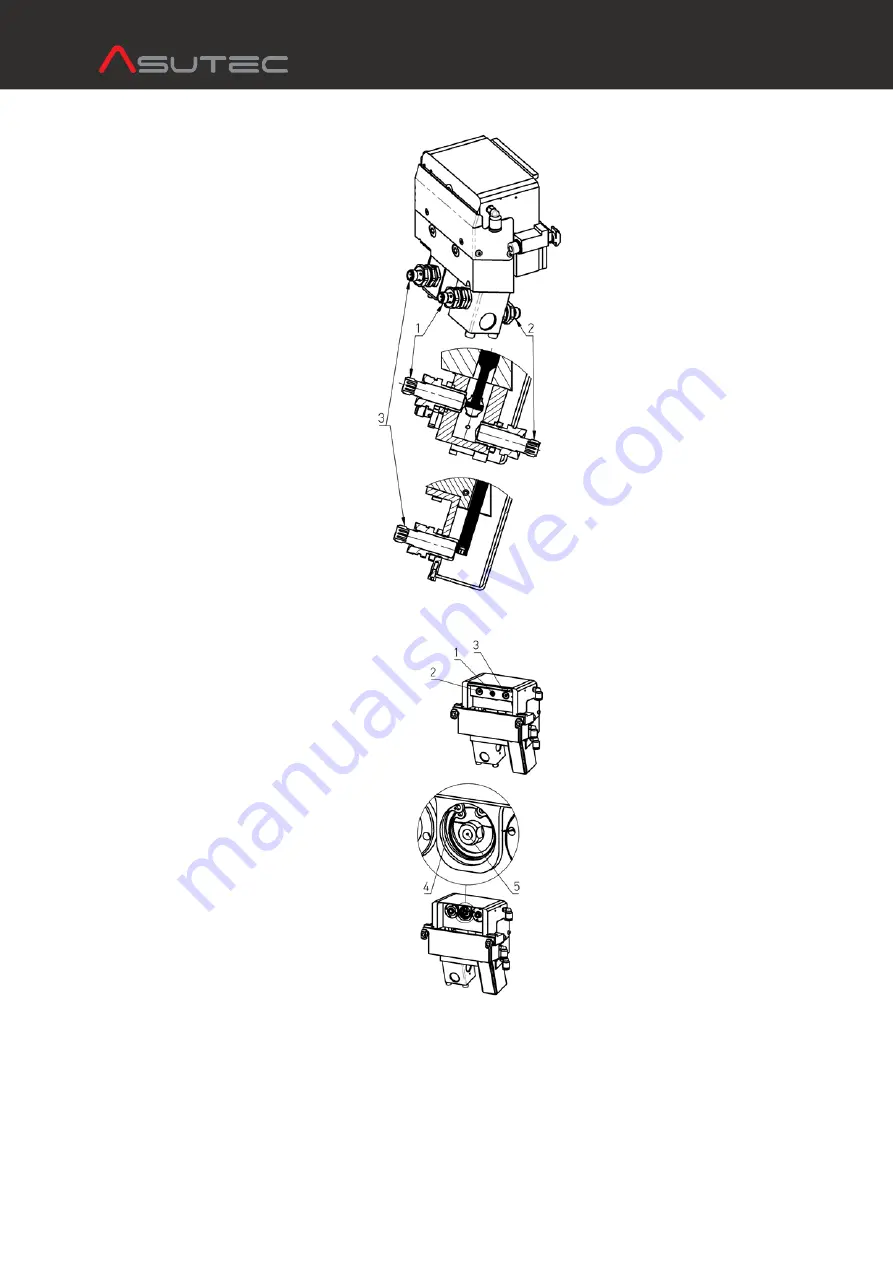
Die Klemmhalter für die obere (1) und für die
abgesenkte Position (2) werden in den
Befestigungsblock bis auf Anschlag
eingeschraubt. Es besteht die Möglichkeit die
Klemmhalter seitlich oder von vorne und hinten
in den Befestigungsblock zu schrauben.
The mounting clamps for the upper (1) and
lower position (2) are screwed into the
mounting block as far as they will go. There is
the possibility to screw the clamping holders on
the side or from the front and rear in the
mounting block.
Um die eingefahrene Stellung des Anschlags
abzufragen, wird der Klemmhalter M16x1 in die
dafür vorgesehene Bohrung geschraubt (3).
Hierbei ist zu beachten, dass in diesem Fall keine
mechanische Begrenzung vorhanden ist, die die
Einschraubtiefe des Klemmhalters vorgibt.
Bei der Montage des Klemmhalters ist in diesem
Fall folgedermaßen vorzugehen:
- schieben Sie den Anschlag in seine
eingefahrene Position.
- schrauben Sie den Klemmhalter soweit
hinein, bis er die Abfragestange berührt.
- Schrauben Sie den Klemmhalter etwa eine
Umdrehung zurück, um somit einen Schalt-
abstand von ca. 1mm einzustellen.
- Kontern Sie den Klemmhalter mit einer
Mutter und montieren Sie den Sensor.
In order to detect the retracted position of the
stop, the mounting clamp M16x1 is screwed
into the bore provided for this purpose (3).
In this case, it should be noted that in this case
there is no mechanical limitation which specifies
the screw depth of the mounting clamp.
When mounting the clamp, the following
procedure should be followed:
- Slide the stop to its retracted position.
- Screw the mounting clamp in until it touches
the query shaft.
-
Screw the mounting clamp back
approximately one revolution, in order to set
a switching distance of approx. 1 mm.
- Lock the clamp with a nut and mount the
sensor.
5.5
TAUSCH DER DÄMPFEINHEIT
5.5
EXCHANGE OF DAMPING UNIT
Werkstückträger werden vom
Verschiebeanschlag gedämpft und gestoppt.
Die Dämpfung übernimmt eine hydraulische
Dämpfeinheit. Je nach Belastung und
Einsatzbedingungen ist bei Verschleiß die
Dämpfeinheit zu tauschen.
Die Austausch-Dämpfeinheit können Sie bei
ASUTEC unter der Artikelbezeichnung
„ASHD-160-11“ bestellen.
Bei dem Austausch der Dämpfeinheit gehen Sie
folgendermaßen vor:
- lösen Sie die mittlere Schraube (1) und die
beiden äußeren Schrauben (2 und 3).
- entnehmen Sie den Anschlag und legen ihn
beiseite.
- demontieren Sie den Sicherungsring (4)
- Drehen Sie die Schraube (1) in die
Kolbenstange der Dämpfeinheit (5) und
ziehen Sie die Dämpfeinheit heraus.
Die Montage der neuen Dämpfeinheit erfolgt
analog der obigen Schritte, in umgekehrter
Reihenfolge. Bitte beachten Sie, dass die mittlere
Schraube (1) nach dem Anziehen noch Spiel hat.
Dies ist beabsichtigt und hat die Funktion einer
Kupplung.
Workpiece carriers are damped and stopped by
the slide stop. A hydraulic damping unit is
mounted in the device. Depending on load and
operating conditions, the damping unit must be
replaced when worn.
The replacement damping unit can be ordered
from ASUTEC with the article code
"ASHD-160-11"
When replacing the damping unit, proceed as
follows:
- Loosen the middle screw (1) and the two outer
screws (2 and 3).
- Remove the stop and set it aside.
- Disassemble the retaining ring (4)
- Turn the screw (1) into the piston rod of the
damping unit (5) and pull out the damping
unit.
The assembly of the new steam unit takes place
in the same way as the above steps, in reverse
order. Please note that the center bolt (1) still
has clearance after tightening. This is intended
and has the function of a coupling.


