background image

ASUS KFN4-D16 Series

4-11

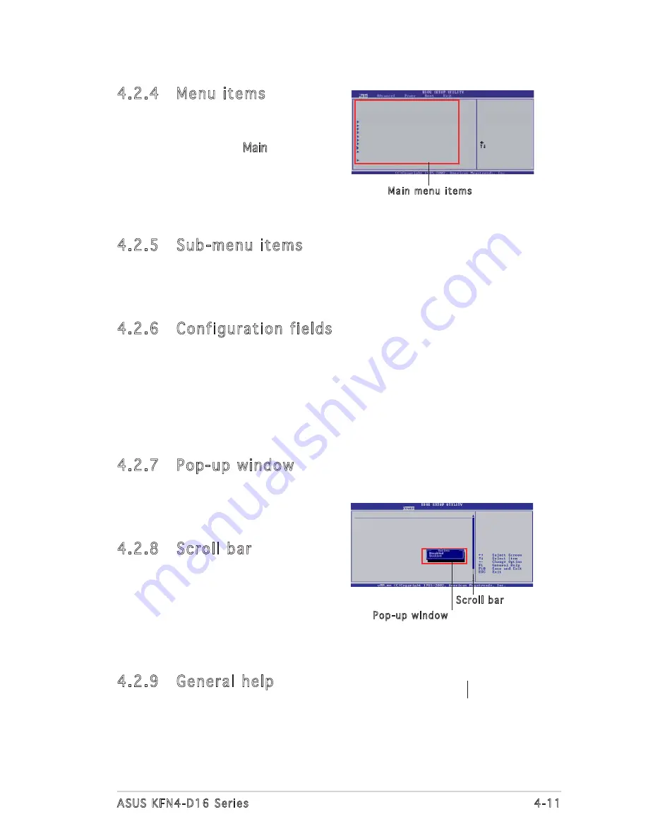
4.2.4  Menu items

The highlighted item on the menu bar  

displays the specific items for that menu. 

For example, selecting Main shows the 

Main menu items.
The other items (Advanced, Power, Boot, 

and Exit) on the menu bar have their 

respective menu items.

4.2.5  Sub-menu items

A solid triangle before each item on any menu screen means that the 

iteam has a sub-menu. To display the sub-menu, select the item and press 

<Enter>.

4.2.6  Configuration fields

These fields show the values for the menu items. If an item is user- 

configurable, you can change the value of the field opposite the item. �ou 

cannot select an item that is not user-configurable.
A configurable field is enclosed in brackets, and is highlighted when 

selected. To change the value of a field, select it then press <Enter> to 

display a list of options. Refer to “4.2.7 Pop-up window.”

4.2.7  Pop-up window

Select a menu item then press <Enter> 

to display a pop-up window with the 

configuration options for that item.

4.2.8  Scroll bar

A scroll bar appears on the right side 

of a menu screen when there are items 

that do not fit on the screen. Press 

the Up/Down arrow keys or <Page 

Up>/<Page Down> keys to display the 

items on the screen.

4.2.9  General help

At the top right corner of the menu screen is a brief description of the 

selected item.

System Time                 [04:10:52]

System Date                 [Wed 02/15/2006]

Legacy Diskette A           [1.44M, 3.5 in]

Language                    [English]

   Primary IDE Master      :[Not Detected]

   Primary IDE Slave       :[Not Detected]

   Secondary IDE Master    :[Not Detected]

   Secondary IDE Slave     :[Not Detected]

   Third IDE Master        :[Not Detected]

   Fourth IDE Master       :[Not Detected] 

   Fifth IDE Master        :[Not Detected]

   Sixth IDE Master        :[Not Detected] 


Use [ENTER], [TAB]

or [SHIFT-TAB] to

select a field.

Use [+] or [-] to

configure system time.

     Select Screen

     Select Item

+-   Change Field

Tab  Select Field

F1   General Help

F10  Save and Exit

ESC  Exit

   IDE Configuration      


   System Information      


Main menu items

Hardware Monitor

CPU1 Temperature      [38ºC/100ºF]

CPU2 Temperature      [41ºC/105.5ºF]

MB Temperature        [47ºC/114ºF]

CPU Fan1 Speed         [3884RPM]

CPU Fan2 Speed         [3648RPM]

Front Fan1 Speed       [1917RPM]

Front Fan2 Speed       [N/A]

Rear Fan1 Speed        [N/A]

Rear Fan2 Speed        [N/A]

Smart Fan Control      [Enabled]


CPU Target Temperature [045]


Pop-up window

Scroll bar

Summary of Contents for KFN4-D16 - Extended

Page 1: ...Motherboard KFN4 D16 Series ...

Page 2: ...CHANTABILITY OR FITNESS FOR A PARTICULAR PURPOSE IN NO EVENT SHALL ASUS ITS DIRECTORS OFFICERS EMPLOYEES OR AGENTS BE LIABLE FOR ANY INDIRECT SPECIAL INCIDENTAL OR CONSEQUENTIAL DAMAGES INCLUDING DAMAGES FOR LOSS OF PROFITS LOSS OF BUSINESS LOSS OF USE OR DATA INTERRUPTION OF BUSINESS AND THE LIKE EVEN IF ASUS HAS BEEN ADVISED OF THE POSSIBILITY OF SUCH DAMAGES ARISING FROM ANY DEFECT OR ERROR IN ...

Page 3: ... 2 1 Placement direction 2 3 2 2 2 Screw holes 2 3 2 2 3 Motherboard layout 2 4 2 2 4 Layout Contents 2 7 2 3 Central Processing Unit CPU 2 8 2 3 1 Installing the CPU 2 8 2 3 2 Installing the CPU heatsink and fan 2 11 2 4 System memory 2 13 2 4 1 Overview 2 13 2 4 2 Memory Configurations 2 14 2 4 3 Installing a DIMM 2 16 2 4 4 Removing a DIMM 2 16 2 5 Expansion slots 2 17 2 5 1 Installing an expan...

Page 4: ... 1 2 AFUDOS utility 4 2 4 1 3 ASUS CrashFree BIOS 2 utility 4 4 4 1 4 ASUS Update utility 4 6 4 2 BIOS setup program 4 9 4 2 1 BIOS menu screen 4 10 4 2 2 Menu bar 4 10 4 2 3 Navigation keys 4 10 4 2 4 Menu items 4 11 4 2 5 Sub menu items 4 11 4 2 6 Configuration fields 4 11 4 2 7 Pop up window 4 11 4 2 8 Scroll bar 4 11 4 2 9 General help 4 11 4 3 Main menu 4 12 4 3 1 System Time 4 12 4 3 2 Syste...

Page 5: ...iguration 4 30 4 6 3 Security 4 31 4 7 Exit menu 4 33 Chapter 5 RAID configuration 5 1 Setting up RAID 5 1 5 1 1 RAID definitions 5 1 5 1 2 Installing hard disk drives 5 2 5 1 3 RAID configuration utility 5 2 5 2 NVIDIA RAID Configurations 5 2 5 2 1 Setting the BIOS RAID items 5 2 5 2 2 Entering the NVIDIA RAID Utility 5 3 5 2 3 Creating a RAID 0 set Stripe 5 4 5 2 4 Creating a RAID 1 set Mirror 5...

Page 6: ...Creating a RAID driver disk 6 1 6 1 2 Installing the RAID controller driver 6 2 6 2 LAN driver installation 6 10 6 2 1 Windows 2000 2003 Server 6 10 6 2 2 Red Hat Enterprise ver 3 0 6 11 6 3 VGA driver installation 6 12 6 3 1 Windows 2000 2003 Server 6 12 6 4 Management applications and utilites installation 6 15 6 4 1 Running the support CD 6 15 6 4 2 Drivers menu 6 15 ...

Page 7: ...ause harmful interference to radio or television reception which can be determined by turning the equipment off and on the user is encouraged to try to correct the interference by one or more of the following measures Reorient or relocate the receiving antenna Increase the separation between the equipment and receiver Connect the equipment to an outlet on a circuit different from that to which the...

Page 8: ...cal power company If the power supply is broken do not try to fix it by yourself Contact a qualified service technician or your retailer Operation safety Before installing the motherboard and adding devices on it carefully read all the manuals that came with the package Before using the product make sure all cables are correctly connected and the power cables are not damaged If you detect any dama...

Page 9: ...ttings through the BIOS Setup menus Detailed descriptions of the BIOS parameters are also provided Chapter 5 RAID configuration Provides information on RAID configurations for this motherboard Chapter 6 Driver installation This chapter provides information on RAID and LAN driver installation for this motherboard Appendix Reference information This appendix includes additional information that you ...

Page 10: ...ey Key1 Key2 Key3 If you must press two or more keys simultaneously the key names are linked with a plus sign Example Ctrl Alt Del Command Means that you must type the command exactly as shown then supply the required item or value enclosed in brackets Example At the DOS prompt type the command line format A S DANGER WARNING Information to prevent injury to yourself when trying to complete a task ...

Page 11: ...4 D16 and KFN4 D16 SAS models only 3 x PCI X slots 133 MHz 100MHz 64 bit 3 3V 1 x PCI slot 33MHz 32 bit 5V PCI 2 3 Dual Onboard BCM5721 Gigabit PCI E LAN controllers 2 x USB 2 0 ports on the rear panel 2 x USB 2 0 connector on board ASUS Smart Fan Technology ASUS CrashFree BIOS 2 ASUS MyLogo2 ASUS CPU Overheating Protection C O P BIOS Recovery CPU Warning LED AMI BIOS 8 MB LPC Green PnP DMI SMBIOS...

Page 12: ...in ATX 12V power connector 2 x USB 2 0 connectors 1 x SMBus header for power supply unit 1 x ASMB3 optional 2 x Front fan connectors 2 x Rear fan connectors 1 x Serial Port COM2 1 x Auxiliary panel connector 1 x System panel connector KFN4 D16 SAS model only 2 x 4in1 mini SAS connector 1 x Serial port 1 x VGA port 2 x USB 2 0 ports 1 x PS 2 keyboard port 1 x PS 2 mouse port SSI power supply with 2...

Page 13: ...1 Product introduction This chapter describes the motherboard features and the new technologies it supports ...

Page 14: ...ASUS KFN4 D16 Series Chapter summary 1 1 1 Welcome 1 1 1 2 Package contents 1 1 1 3 Special features 1 2 ...

Page 15: ...our package with the list below 1 2 Package contents Check your motherboard package for the following items If any of the above items is damaged or missing contact your retailer KFN4 D16 SAS KFN4 D16 KFN4 D16 1U Cables Serial ATA signal cable 4 4 4 Serial ATA power cable 2 2 2 SAS cable 2 3 in 1 Floppy Ultra ATA disk drive cable 1 1 1 Accessories I O shield 1 1 1 Application CD KFN4 D16 support CD...

Page 16: ... GB s PCI Express interface The motherboard fully supports PCI Express the latest I O interconnect technology that speeds up the PCI bus PCI Express features point to point serial interconnections between devices and allows higher clockspeeds by carrying data in packets This high speed interface is software compatible with existing PCI or PCI X specifications Serial Attached SCSI SAS technology su...

Page 17: ...l allows RAID 0 RAID 1 RAID 0 1 RAID 5 and JBOD configuration for four SATA connectors The LSISAS1068 is an eight port 3 0 Gbit s SAS SATA controller that is compliant with the Fusion MPT architecture and supports the Integrated RAID solution IR The LSI Logic Integrated RAID solution provides cost benefits for the server or workstation market where the extra performance storage capacity and or red...

Page 18: ... motherboard allows you to personalize and add style to your system with customizable boot logos USB 2 0 technology The motherboard implements the Universal Serial Bus USB 2 0 specification dramatically increasing the connection speed from the 12 Mbps bandwidth on USB 1 1 to a fast 480 Mbps on USB 2 0 USB 2 0 is backward compatible with USB 1 1 Temperature fan and voltage monitoring The CPU temper...

Page 19: ... Hardware information This chapter lists the hardware setup procedures that you have to perform when installing system components It includes description of the jumpers and connectors on the motherboard ...

Page 20: ...N4 D16 Series Chapter summary 2 1 Before you proceed 2 1 2 2 Motherboard overview 2 3 2 3 Central Processing Unit CPU 2 8 2 4 System memory 2 13 2 5 Expansion slots 2 17 2 6 Jumpers 2 21 2 7 Connectors 2 26 2 ...

Page 21: ...e a grounded wrist strap or touch a safely grounded object or a metal object such as the power supply case before handling components to avoid damaging them due to static electricity Hold the components by the edges to avoid touching the ICs on them Whenever you uninstall any component place it on a grounded antistatic pad or in the bag that came with the component Before you install or remove any...

Page 22: ...f mode This is a reminder that you should shut down the system and unplug the power cable before removing or plugging in any motherboard component 2 CPU warning LED CPU_WARN1 The CPU warning LED lights up to indicate that a processor is not installed or the processor is not installed properly in CPU 1 socket 2 HB_LED The HB_LED blinks per second to indicate that the LSI1068 chipset has started wor...

Page 23: ...orientation The edge with external ports goes to the rear part of the chassis as indicated in the image below 2 2 2 Screw holes Place ten 10 screws into the holes indicated by circles to secure the motherboard to the chassis Place this side towards the rear of the chassis Do not overtighten the screws Doing so can damage the motherboard Make sure to unplug the power cord before installing or remov...

Page 24: ...ule DDR2 DIMM_B5 128 bit 240 pin module DDR2 DIMM_A6 128 bit 240 pin module DDR2 DIMM_B6 128 bit 240 pin module DDR2 DIMM_A7 128 bit 240 pin module DDR2 DIMM_B7 128 bit 240 pin module DDR2 DIMM_A8 128 bit 240 pin module DDR2 DIMM_B8 128 bit 240 pin module DDR2 DIMM_B4 128 bit 240 pin module DDR2 DIMM_A4 128 bit 240 pin module DDR2 DIMM_B3 128 bit 240 pin module DDR2 DIMM_A3 128 bit 240 pin module ...

Page 25: ...t 240 pin module DDR2 DIMM_A2 128 bit 240 pin module DDR2 DIMM_B1 128 bit 240 pin module DDR2 DIMM_A1 128 bit 240 pin module ATXPWR1 ATX12V1 CPU_FAN2 KBPWR1 FM_CPU2 PCI E1 HTX1 PCI1 PCIX1 PCIX2 ZCR_PCIX1 HTX2 LAN_EN1 VGA_EN1 LAN_EN2 SUPER I O 8Mb BIOS REAR_FAN2 REAR_FAN1 PANEL1 COM2 PSUSMB1 BPSMB1 CPU_WARN1 SB_PWR1 AUX_PANEL1 SAS_LED1 SAS_EN1 HB_LED1 SAS_UART1 SAS_2 SAS_1 FLOPPY PRI_IDE1 SEC_IDE1 ...

Page 26: ...3 128 bit 240 pin module DDR2 DIMM_B2 128 bit 240 pin module DDR2 DIMM_A2 128 bit 240 pin module DDR2 DIMM_B1 128 bit 240 pin module DDR2 DIMM_A1 128 bit 240 pin module ATXPWR1 ATX12V1 CPU_FAN2 KBPWR1 FM_CPU2 PCI E1 HTX1 HTX2 LAN_EN1 VGA_EN1 LAN_EN2 SUPER I O 8Mb BIOS REAR_FAN2 REAR_FAN1 PANEL1 COM2 PSUSMB1 BPSMB1 CPU_WARN1 SB_PWR1 AUX_PANEL1 FLOPPY PRI_IDE1 SEC_IDE1 SATA3 SATA4 SATA2 SATA1 FRNT_F...

Page 27: ...2 0 ports 1 and 2 2 26 4 Serial COM 1 port 2 26 5 VGA port 2 26 6 LAN1 RJ 45 port 2 26 7 LAN2 RJ 45 port 2 26 Internal connectors Page 1 Floppy disk drive connector 34 1 pin FLOPPY1 2 27 2 IDE connectors 40 1 pin PRI_IDE1 SEC_IDE1 2 27 3 SAS LSI1068 ports LED connector 18 1 pin SASLED1 KFN4 D16 SAS model only 2 28 4 Serial ATA connectors 4 SATA SATA1 SATA2 SATA3 SATA 4 2 29 5 CPU Front and Rear fa...

Page 28: ...e socket and the socket contacts are not bent Contact your retailer immediately if the PnP cap is missing or if you see any damage to the PnP cap socket contacts motherboard components ASUS shoulders the repair cost only if the damage is shipment transit related Keep the cap after installing the motherboard ASUS will process Return Merchandise Authorization RMA requests only if the motherboard com...

Page 29: ...then push the PnP cap from the load plate window to remove B Load plate A B 2 Press the load lever with your thumb A then move it to the left B until it is released from the retention tab Retention tab Load lever This side of the socket box should face you PnP cap A B To prevent damage to the socket pins do not remove the PnP cap unless you are installing a CPU ...

Page 30: ... socket The socket alignment keys should fit into the CPU notches Gold triangle mark Alignment keys The CPU fits in only one correct orientation DO NOT force the CPU into the socket to prevent bending the connectors on the socket and damaging the CPU 6 Close the load plate A then push the load lever B until it snaps into the retention tab A B ...

Page 31: ...The retention module base is already installed on the motherboard upon purchase You do not have to remove the retention module base when installing the CPU or installing other motherboard components If you purchased a separate CPU heatsink and fan assembly make sure that a Thermal Interface Material is properly applied to the CPU heatsink or CPU before you install the heatsink and fan assembly You...

Page 32: ...bracket lock to the retention module base A clicking sound denotes that the retention bracket is in place 4 Push down the retention bracket lock on the retention mechanism to secure the heatsink and fan to the module base Make sure that the fan and heatsink assembly perfectly fits the retention mechanism module base otherwise you cannot snap the retention bracket in place ...

Page 33: ...o may cause hardware monitoring errors KFN4 D16 SAS KFN4 D16 Series CPU Fan Connectors CPU_FAN2 CPU_FAN1 GND CPU FAN PWR CPU FAN IN CPU FAN PWM GND CPU FAN PWR CPU FAN IN CPU FAN PWM 2 4 System memory 2 4 1 Overview The motherboard comes with sixteen 240 pin Double Data Rate II DDR2 Dual Inline Memory Modules DIMM sockets The following figure illustrates the location of the sockets KFN4 D16 SAS KF...

Page 34: ...r dual channel configuration the total size of memory module s installed per channel must be the same for better performance Single CPU DIMM_A1 DIMM_B1 DIMM_A2 DIMM_B2 DIMM_A3 DIMM_B3 DIMM_A4 DIMM_B4 Dual CPU DIMM_A5 DIMM_B5 DIMM_A6 DIMM_B6 DIMM_A7 DIMM_B7 DIMM_A8 DIMM_B8 Always install DIMMs with the same CAS latency For optimum compatibility we recommend that you obtain memory modules from the s...

Page 35: ... 15 Recommended memory configuration for CPU2 Mode Populated DIMM Qty A5 B5 A6 B6 A7 B7 A8 B8 Single channel 1 V 2 V V 3 V V V 4 V V V V Double channel 2 V V 4 V V V V 6 V V V V V V 8 V V V V V V V V V DIIMM module populated ...

Page 36: ...ing clips snap back in place and the DIMM is properly seated 2 4 4 Removing a DIMM Follow these steps to remove a DIMM 1 Simultaneously press the retaining clips outward to unlock the DIMM 2 Remove the DIMM from the socket A DDR2 DIMM is keyed with a notch so that it fits in only one direction DO NOT force a DIMM into a socket to avoid damaging the DIMM The DDR2 DIMM sockets do not support DDR DIM...

Page 37: ... and press firmly until the riser card is completely seated on the slot 5 Align the card connector with the slot on the riser card and press firmly until the card is completely seated on the riser card slot 6 Secure the card to the chassis with the screw you removed earlier 7 Replace the system cover 2 5 2 Configuring an expansion card After installing the expansion card configure it by adjusting ...

Page 38: ... Time Clock 9 4 IRQ holder for PCI steering 10 5 IRQ holder for PCI steering 11 6 IRQ holder for PCI steering 12 7 PS 2 Compatible Mouse Port 13 8 Numeric Data Processor 14 9 Primary IDE Channel 15 10 Secondary IDE Channel 2 5 4 PCI PCI X slots The PCI PCI X slots supports cards such as a LAN card SCSI card USB card and other cards that comply with PCI 2 3 and PCI X 1 0 specifications The figure s...

Page 39: ...MHz When all PCI X slot is populated the PCI X frequency is 66MHz Refer to the table below for details PCI X 1 slot PCIX1 PCI X 1 slot PCIX2 PCI X 1 slot ZCR_PCIX1 Frequency populated 133MHz populated populated populated populated 100MHz populated populated populated populated populated populated populated PCI X Frequency KFN4 D16 SAS model PCI X 1 slot PCIX1 PCI X 1 slot PCIX2 PCI X 1 slot ZCR_PC...

Page 40: ...s x 16 slot Due to hardware limitation the PCI Express x 16 slot only runs at x8 x4 and x1 speeds 2 5 6 ZCR slot KFN4 D16 SAS model The 64 bit PCI X slot green on the motherboard supports a Zero Channel RAID card that allows RAID0 RAID1 RAID10 RAID5 and JBOD configurations 2 5 7 HTX slot The HTX slot supports HTX InfiniBand card that complies with HTX interface specifications The figure shows an I...

Page 41: ...1 Turn OFF the computer and unplug the power cord 2 Remove the onboard battery 3 Move the jumper cap from pins 1 2 default to pins 2 3 Keep the cap on pins 2 3 for about 5 10 seconds then move the cap back to pins 1 2 4 Re install the battery 5 Plug the power cord and turn ON the computer 6 Hold down the Del key during the boot process and enter BIOS setup to re enter data Except when clearing the...

Page 42: ...n ATX power supply that can supply at least 1A on the 5VSB lead and a corresponding setting in the BIOS 3 Gigabit LAN controller setting 3 pin LAN_EN1 LAN_EN2 These jumpers allow you to enable or disable the onboard Broadcom BCM5721 Gigabit LAN controllers The LAN_EN1 jumper controls the LAN1 port The LAN_EN2 iumper controls the LAN2 port KBPWR1 Default 5V 5V_Dual 2 1 3 2 LAN_EN1 Enabled Default 1...

Page 43: ...o connect either a 3 pin or a 4 pin fan cable plug to the CPU fan connectors CPU_FAN1 CPU_FAN2 Set these jumpers to pins 1 2 if you are using a 3 pin fan cable plug or to pins 2 3 if you are using a 4 pin plug KFN4 D16 Series LAN_EN2 Setting KFN4 D16 Series FM_CPU Settings FM_CPU2 DC MODE PWM MODE 1 2 3 2 1 2 2 3 FM_CPU1 PWM MODE DC MODE ...

Page 44: ...3 default to pins 1 2 3 Insert a floppy disk with the original or updated BIOS file 4 Plug the power cord and turn ON the computer 5 The system searches for the BIOS file in the floppy then reflashes the BIOS 6 When finished shut down your computer 7 Replace the jumper cap from pins 1 2 to pins 2 3 8 Reboot your computer 9 Hold down the Del key during the boot process and enter BIOS setup to re en...

Page 45: ...board ATI ES1000 video graphics controller VGA_EN1 Default Disabled Enabled 1 2 2 3 7 SAS controller setting 3 pin SAS_EN1 KFN4 D16 SAS model only This jumper allows you to enable or disable the onboard LSI SAS1068 chip KFN4 D16 Series VGA Setting SAS_EN1 Default Disabled Enabled 1 2 2 3 KFN4 D16 Series SAS Controller Setting ...

Page 46: ...devices 6 LAN1 RJ 45 port Supported by the BROADCOM BCM5721 Gigabit LAN controller this port allows Gigabit connection to a Local Area Network LAN through a network hub Refer to the table below for the LAN port LED indications 7 LAN2 RJ 45 port Supported by the BROADCOM BCM5721 Gigabit LAN controller this port allows Gigabit connection to a Local Area Network LAN through a network hub Refer to the...

Page 47: ...ncorrect cable connection when using a FDD cable with a covered Pin 5 NOTE Orient the red markings on the floppy ribbon cable to PIN 1 PIN 1 FLOPPY 2 IDE connectors 40 1 pin PRI_IDE1 SEC_IDE1 The onboard IDE connector is for Ultra DMA 133 100 66 signal cable There are three connectors on each Ultra DMA 133 100 66 signal cable blue black and gray Connect the blue connector to the motherboard s IDE ...

Page 48: ...e LOW Activity LED signals are nominally configured to indicate SAS link activity Pin 20 on the IDE connector is removed to match the covered hole on the Ultra DMA cable connector This prevents incorrect insertion when you connect the IDE cable Use the 80 conductor IDE cable for Ultra DMA 133 100 66 IDE devices If any device jumper is set as Cable Select make sure all other device jumpers have the...

Page 49: ... connectors If you intent to create a Serial ATA RAID set using these connectors enable the RAID function of each port from the nVidia RAID Setup sub menu item in the BIOS See section 4 3 5 IDE Configuration on page 4 14 for details 5 CPU Front and Rear fan connectors 4 pin CPU_FAN1 2 3 pin FRNT_FAN1 2 3 pin REAR_FAN1 2 The fan connectors support cooling fans of 350mA 2000mA 24 W max or a total of...

Page 50: ...ices Devices communicate with an SMBus host and or other SMBus devices using the SMBus interface 7 USB connectors 10 1 pin USB3 USB4 These connectors are for USB 2 0 ports These connectors comply with the USB 2 0 specification that supports up to 480 Mbps connection speed KFN4 D16 SAS CPU_FAN1 CPU_FAN2 REAR_FAN2 REAR_FAN1 FRNT_FAN1 FRNT_FAN2 GND Rotation 12V GND Rotation 12V GND Rotation 12V GND R...

Page 51: ...nd is always lit when linked LAN2 link activity LED 2 pin LAN2_LINKACTLED This 2 pin connector is for the LAN2 Activity LED Connect the LAN2 Activity LED cable to this connector This connector blinks during a network activity and lights up when linked Locator LED 1 2 pin LOCATORLED1 This 2 pin connector is for the Locator LED 1 Connect the Locator LED 1 cable to this connector This LED lights up w...

Page 52: ...mode Hard disk drive activity Red 2 pin HDDLED This 2 pin connector is for the HDD Activity LED Connect the HDD Activity LED cable to this connector The IDE LED lights up or flashes when data is read from or written to the HDD If an optional SATA add in card is installed the read or write activities of any device connected to the SATA add in card causes this LED to light up System warning speaker ...

Page 53: ...n SSI 12 V Specification 2 0 compliant power supply unit PSU that provides a minimum power of 450 W is recommended for a fully configured system By default four ATX12V1 connector pins are covered to prevent incorrent insertion of a 4 pin ATX 12V power plug Remove this cover when using a PSU with an 8 pin ATX 12V power plug Do not forget to connect the 4 pin or 8 pin ATX 12 V power plug otherwise t...

Page 54: ... the back of the system chassis 12 Power supply SMBus connector 5 pin PSUSMB1 This connector allows you to connect SMBus System Management Bus devices to the power supply unit Devices communicate with an SMBus host and or other SMBus devices using the SMBus interface KFN4 D16 Series Serial port connectors PIN 1 COM2 KFN4 D16 Series Power supply SMBus connector PSUSMB1 3 3V Remote Sense GND NC I2C_...

Page 55: ...2 While still keeping your thumb s grip on the cable lock carefully pull away the cable from the connector 13 Mini SAS connectors KFN4 D16 SAS model only This motherboard comes with two Serial Attached SCSI SAS connectors the next generation storage technology that supports both Serial Attached SCSI and Serial ATA Each connector supports up to four 4 devices KFN4 D16 Series Mini SAS connectors Min...

Page 56: ...3 Powering up This chapter describes the power up sequence the vocal POST messages and ways of shutting down the system ...

Page 57: ...ASUS KFN4 D16 Series Chapter summary 3 3 1 Starting up for the first time 3 1 3 2 Powering off the computer 3 2 ...

Page 58: ...s with green standards or if it has a power standby feature the monitor LED may light up or switch between orange and green after the system LED turns on The system then runs the Power On Self Test POST While the tests are running the BIOS beeps or additional messages appear on the screen If you do not see anything within 30 seconds from the time you turned on the power the system may have failed ...

Page 59: ...ndows XP 1 Click the Start button then select Turn Off Computer 2 Click the Turn Off button to shut down the computer 3 The power supply should turn off after Windows shuts down 3 2 2 Using the dual function power switch While the system is ON pressing the power switch for less than four seconds puts the system to sleep mode or to soft off mode depending on the BIOS setting Pressing the power swit...

Page 60: ...4 BIOS setup This chapter tells how to change the system settings through the BIOS Setup menus Detailed descriptions of the BIOS parameters are also provided ...

Page 61: ...US KFN4 D16 Series Chapter summary 4 4 1 Managing and updating your BIOS 4 1 4 2 BIOS setup program 4 9 4 3 Main menu 4 12 4 4 Advanced menu 4 16 4 5 Power menu 4 25 4 6 Boot menu 4 29 4 7 Exit menu 4 33 ...

Page 62: ... to the floppy disk drive b Click Start from the Windows desktop then select My Computer c Select the 3 1 2 Floppy Drive icon d Click File from the menu then select Format A Format 3 1 2 Floppy Disk window appears e Windows XP users Select Create an MS DOS startup disk from the format options field then click Start Windows 2000 environment To create a set of boot disks for Windows 2000 a Insert a ...

Page 63: ...then at the prompt type afudos o filename where the filename is any user assigned filename not more than eight alphanumeric characters for the main filename and three alphanumeric characters for the extension name A afudos oOLDBIOS1 rom Make sure that the floppy disk is not write protected and has at least 1 1MB free space to save the file The succeeding BIOS screens are for reference only The act...

Page 64: ...le for the motherboard Save the BIOS file to a bootable floppy disk A afudos iKFN4 D16 ROM Write the BIOS filename on a piece of paper You need to type the exact BIOS filename at the DOS prompt A afudos iKFN4 D16 ROM AMI Firmware Update Utility Version 1 19 ASUS V2 07 03 11 24BB Copyright C 2002 American Megatrends Inc All rights reserved WARNING Do not turn off power during flash BIOS Reading fil...

Page 65: ...corrupted during the updating process You can update a corrupted BIOS file using the motherboard support CD or the floppy disk that contains the updated BIOS file Recovering the BIOS from a floppy disk To recover the BIOS from a floppy disk 1 Turn on the system 2 Insert the floppy disk with the original or updated BIOS file to the floppy disk drive 3 The utility displays the following message and ...

Page 66: ...matically checks the floppy disk for the original or updated BIOS file When no floppy disk is found the utility automatically checks the optical drive for the original or updated BIOS file The utility then updates the corrupted BIOS file Bad BIOS checksum Starting BIOS recovery Checking for floppy The recovered BIOS may not be the latest BIOS version for this motherboard Visit the ASUS website www...

Page 67: ...date the motherboard BIOS in Windows environment The ASUS Update utility allows you to Save the current BIOS file Download the latest BIOS file from the Internet Update the BIOS from an updated BIOS file Update the BIOS directly from the Internet and View the BIOS version information This utility is available in the support CD that comes with the motherboard package ASUS Update requires an Interne...

Page 68: ...ext Updating the BIOS through the Internet To update the BIOS through the Internet 1 Launch the ASUS Update utility from the Windows desktop by clicking Start Programs ASUS ASUSUpdate ASUSUpdate The ASUS Update main window appears 2 Select Update BIOS from the Internet option from the drop down menu then click Next ...

Page 69: ...te BIOS from a file option from the drop down menu then click Next 4 From the FTP site select the BIOS version that you wish to download Click Next 5 Follow the screen instructions to complete the update process The ASUS Update utility is capable of updating itself through the Internet Always update the utility to avail all its features 3 Locate the BIOS file from the Open window then click Save 4...

Page 70: ...ram Press Del during the Power On Self Test POST to enter the Setup utility otherwise POST continues with its test routines If you wish to enter Setup after POST restart the system by pressing Ctrl Alt Del or by pressing the reset button on the system chassis You can also restart by turning the system off and then back on Do this last option only if the first two failed The Setup program is design...

Page 71: ... of a menu screen are the navigation keys for that particular menu Use the navigation keys to select items in the menu and change the settings 4 2 1 BIOS menu screen Some of the navigation keys differ from one screen to another System Time 04 10 52 System Date Wed 02 15 2006 Legacy Diskette A 1 44M 3 5 in Primary IDE Master Not Detected Primary IDE Slave Not Detected Secondary IDE Master Not Detec...

Page 72: ...ar A scroll bar appears on the right side of a menu screen when there are items that do not fit on the screen Press the Up Down arrow keys or Page Up Page Down keys to display the items on the screen 4 2 9 General help At the top right corner of the menu screen is a brief description of the selected item System Time 04 10 52 System Date Wed 02 15 2006 Legacy Diskette A 1 44M 3 5 in Language Englis...

Page 73: ...in 1 2M 5 25 in 720K 3 5 in 1 44M 3 5 in 2 88M 3 5 in Refer to section 4 2 1 BIOS menu screen for information on the menu screen items and how to navigate through them System Time 04 10 52 System Date Wed 02 15 2006 Legacy Diskette A 1 44M 3 5 in Primary IDE Master Not Detected Primary IDE Slave Not Detected Secondary IDE Master Not Detected Secondary IDE Slave Not Detected Third IDE Master Not De...

Page 74: ...r a ZIP LS 120 or MO drive Configuration options Not Installed Auto CDROM ARMD LBA Large Mode Auto Enables or disables the LBA mode Setting to Auto enables the LBA mode if the device supports this mode and if the device was not previously formatted with LBA mode disabled Configuration options Disabled Auto Block Multi sector Transfer Auto Enables or disables data multi sectors transfers When set t...

Page 75: ... Disabled Enabled SATA0 IDE Interface Enabled Enables or disables the SATA0 IDE Interface Configuration options Disabled Enabled SATA1 IDE Interface Enabled Enables or disables the SATA1 IDE Interface Configuration options Disabled Enabled Hard Disk Write Protect Disabled Enables or disables the hard disk wirte protection This will be effective only if device is accessed through BIOS Configuration...

Page 76: ...ed Enabled The following items appear when the RAID Option ROM is Enabled Third Master as RAID Disabled Sets the third master interface as RAID Configuration options Disabled Enabled Fourth Master as RAID Disabled Sets the fourth master interface as RAID Configuration options Disabled Enabled Fifth Master as RAID Disabled Sets the fifth master interface as RAID Configuration options Disabled Enabl...

Page 77: ...2 System Memory Size 512MB 4 4 Advanced menu The Advanced menu items allow you to change the settings for the CPU and other system devices Take caution when changing the settings of the Advanced menu items Incorrect field values can cause the system to malfunction Configure CPU Select Screen Select Item Enter Go to Sub screen F1 General Help F10 Save and Exit ESC Exit CPU Configuration Chipset Onb...

Page 78: ...d Enables or disables the GART Error reporting feature Configuration options Disabled Enabled MTRR Mapping Continuous Sets the method used for programming CPU MTRRs when 4GB or more memory is installed on the system When set to Discrete the BIOS leaves the PCI hole below the 4GB boundary undescribed Set to Continuous to describe the PCI hole as non cacheable Configuration options Continuous Discre...

Page 79: ...speed will be programmed regardless Memclock Mode Auto Sets the memory clock mode Configuration options Auto Limit Manual The following item appears when the Memclock Mode is set to Limit or Manual Memclock Value 200 MHz Sets the memory clock mode limit Configuration options 200 MHz 266 MHz 333 MHz MCT Timing Mode Auto Sets the MCT Timing Mode Configuration options Auto Limit Bank Interleaving Aut...

Page 80: ... 1 025 V 1 000 V 0 975 V 0 950 V 0 925 V 0 900 V 0 875 V 0 850 V 0 825 V 0 800 V SouthBridge Configuration The SouthBridge Configuration menu allows you to change the SouthBridge settings Select Screen Select Item Change Option F1 General Help F10 Save and Exit ESC Exit South Bridge Configuration SMBus Interface Enabled IOAPIC Enabled CPU Spread Spectrum Disabled SATA Spread Spectrum Disabled PCI ...

Page 81: ...ectrum Disabled Enables or disables the PCI Express spread spectrum Configuration options Disabled Enabled Hyper Transport Configuration The sub menu allows you to change the Hyper Transport settings Select Screen Select Item Change Option F1 General Help F10 Save and Exit ESC Exit Hyper Transport Configuration NODE0 NODE1 HT Link Speed Auto NODE0 NODE1 HT Link Width Auto NODE0 SB HT Link Speed Au...

Page 82: ...ial Port2 IR Mode Configuration options SINB SOUTB IRRX IRTX IR Duplex Mode Half Duplex Allows you to select full or half duplex for Serial Port2 IR Mode Configuration options Half Duplex Full Duplex Onboard VGA Enabled Enables or disables the Onboard VGA Configuration options Disabled Enabled Onboard SAS Enabled Enables or disables the Onboard SAS Configuration options Disabled Enabled Onboard BC...

Page 83: ... Device IRQ 15 assigned to PCI Device NO Lets the BIOS configue all the devices in the system YES Lets the operating system configure Plug and Play PnP devices not required for boot if your system has a Plug and Play operating system Plug And Play O S No When set to No BIOS configures all the devices in the system When set to Yes and if you install a Plug and Play operating system the operating sy...

Page 84: ...IRQ xx assigned to PCI Device When set to PCI Device the specific IRQ is free for use of PCI PnP devices When set to Reserved the IRQ is reserved for legacy ISA devices Configuration options PCI Device Reserved 4 4 5 Trusted Computing Trusted Computing Trusted Computing 4 4 7 Remote Access Configuration The items in this menu allows you to configure the remote access types and parameters Configure...

Page 85: ...w control for console redirection Configuration options None Hardware Software Redirection After BIOS POST Disabled Allows you to set redirection during or after BIOS POST Configuration options Disabled Boot Loader Always Terminal Type ANSI Allows you to select the target terminal type Configuration options ANSI VT100 VT UTF8 VT UTF8 Combo Key Support Disabled Disables or enables the VT UTF8 Combi...

Page 86: ...the USB 2 0 controller mode to HiSpeed 480 Mbps or FullSpeed 12 Mbps Configuration options HiSpeed FullSpeed BIOS EHCI Hand Off Enabled Enables or disables the BIOS EHCI hand off feature Configuration options Enabled Disabled The Module Version and USB Devices Enabled items show the auto detected values If no USB device is detected the USB Devices Enabled item shows None USB Configuration Module V...

Page 87: ...IC table pointer is included in the RSDT pointer list Configuration options Disabled Enabled Do not change the ACPI APIC support after you have installed the operating system OS otherwise a boot failure may occur 4 5 3 ACPI MCFG Support Enabled Allows you to enable or disable the Memory Mapped Configuration MCFG support When set to Enabled the MCFG table pointer is included in the RSDT pointer lis...

Page 88: ...ns Disabled Standby Suspend PME Resume Disabled When set to Enabled the system enables the PME to generate a wake event while the computer is in Soft off mode Configuration options Disabled Enabled Resume On Ring Disabled Allows you to enable or disable the RI to generate a wake event Configuration options Disabled Enabled RTC Resume Disabled Allows you to enable or disable RTC to generate a wake ...

Page 89: ...r disable the PCIE Device to generate a wake event Configuration options Disabled Enabled 4 5 5 Hardware Monitor Use the arrow down key to display additional items 5V Voltage 5 094V 5VSB Voltage 4 980V VBAT Voltage 3 120V 12V Voltage 12 053V Hardware Monitor CPU1 Temperature 38ºC 100ºF CPU2 Temperature 41ºC 105 5ºF MB Temperature 47ºC 114ºF CPU Fan1 Speed 3884RPM CPU Fan2 Speed 3648RPM Front Fan1 ...

Page 90: ...nnected to the motherboard the field shows N A Select Ignored if you do not wish to display the detected temperatures Smart Fan Control Disabled Allows you to enable or disable the ASUS Smart Fan feature that smartly adjusts the fan speeds for more efficient system operation Configuration options Disabled Enabled The CPU Target Temperature and MB Target Temperature items appear when you enabled th...

Page 91: ... 6 2 Boot Settings Configuration Select Screen Select Item Change Option F1 General Help F10 Save and Exit ESC Exit Boot Settings Configuration Quick Boot Enabled Full Screen Logo Enabled Bootup Num Lock On PS 2 Mouse Support Auto Wait For F1 If Error Enabled Hit DEL Message Display Enabled Interrupt 19 Capture Disabled Allows BIOS to skip certain tests while booting This will decrease the time ne...

Page 92: ... Exit Enter to change password Enter again to disabled password Security Settings Supervisor Password Not Installed User Password Not Installed Change Supervisor Password Change User Password Bootup Num Lock On Allows you to select the power on state for the NumLock Configuration options Off On PS 2 Mouse Support Auto Allows you to enable or disable support for PS 2 mouse Configuration options Dis...

Page 93: ...yright 1985 2002 American Megatrends Inc BIOS SETUP UTILITY Boot Security Settings Supervisor Password Not Installed User Password Not Installed Change Supervisor Password User Access Level Full Access Change User Password Password Check Setup Enter to change password Enter again to disabled password User Access Level Full Access This item allows you to select the access restriction to the Setup i...

Page 94: ...lues for the BIOS items and save or discard your changes to the BIOS items To set a User Password 1 Select the Change User Password item and press Enter 2 On the password box that appears type a password composed of at least six letters and or numbers then press Enter 3 Confirm the password when prompted The message Password Installed appears after you set your password successfully To change the ...

Page 95: ... exiting Exit Discard Changes Select this option only if you do not want to save the changes that you made to the Setup program If you made changes to fields other than System Date System Time and Password the BIOS asks for a confirmation before exiting Discard Changes Allows you to discard the selections you made and restore the previously saved values After selecting this option a confirmation a...

Page 96: ...5 RAID support This chapter provides information on RAID configurations for this motherboard ...

Page 97: ...ASUS KFN4 D16 Series Chapter summary 5 5 1 Setting up RAID 5 1 5 2 NVIDIA RAID Configurations 5 2 5 3 LSI Logic MPT Setup Utility 5 10 ...

Page 98: ...e other drive This RAID configuration provides data protection and increases fault tolerance to the entire system Use two new drives or use an existing drive and a new drive for this setup The new drive must be of the same size or larger than the existing drive RAID 0 1 is data striping and data mirroring combined without parity redundancy data having to be calculated and written With the RAID 0 1...

Page 99: ...ty if you installed IDE and or SATA hard disk drives to the IDE and or SATA connectors supported by the NVIDIA MCP55 Professional chip Refer to the succeeding sections for details on how to enter the RAID configuration utility 5 2 NVIDIA RAID configurations The motherboard includes a high performance SATA RAID controller integrated in the NVIDIA CK8 04 PRO chip The RAID controller supports RAID 0 ...

Page 100: ...utility main menu F6 Back F7 Finish TAB Navigate Select ENTER Popup NVIDIA RAID Utility Oct 5 2004 Define a New Array RAID Mode Striping Striping Block Optimal Free Disks Array Disks Loc Disk Model Name Loc Disk Model Name 1 0 M XXXXXXXXXXXXXXXXXX 1 1 M XXXXXXXXXXXXXXXXXX Add 2 0 M XXXXXXXXXXXXXXXXXX 2 1 M XXXXXXXXXXXXXXXXXX Del At the bottom section of the screen are the navigation keys These key...

Page 101: ... RAID 0 set 1 From the Define a New Array menu select RAID Mode then press Enter A pop up menu appears 2 Use the up or down arrow keys to select Striping then press Enter Mirroring Striping Stripe Mirroring Spanning RAID 5 3 Press TAB to move to the Striping Block option then press Enter 4 Use the up or down arrow keys to select the stripe block size appropriate to your drive usage then press Ente...

Page 102: ... to continue creating the RAID set without deleting the data on the disks You will lose all data on the drives if you clear the disk data 9 The utility displays the created RAID 0 set Press Ctrl X to save your settings and exit the utility Ctrl X Exit Select B Set Boot N New Array ENTER Detail NVIDIA RAID Utility Oct 5 2004 Array List Boot Id Status Vendor Array Model Name No 4 Healthy NVIDIA STRI...

Page 103: ...the hard disk drives press F7 to create the RAID 1 set A pop up window appears 6 Press Y to delete all data from the hard disk drives and continue creating the RAID set Press N to backup existing data to a target hard disk drive You will lose all data on the drives if you clear the disk data 7 The utility displays the created RAID 1 set Press Ctrl X to save your settings and exit the utility F6 Ba...

Page 104: ... array or Esc to cancel The Array List screen displays the RAID set after rebuilding Rebuild array Enter OK Esc Cancel Ctrl X Exit Select B Set Boot N New Array ENTER Detail NVIDIA RAID Utility Oct 5 2004 Array List Boot Id Status Vendor Array Model Name No 4 Healthy NVIDIA STRIPING XXX XXG No 3 Healthy NVIDIA MIRRORING XXX XXG Select F6 Back F7 Finish Array 1 NVIDIA MIRROR XXX XXG Array Detail RA...

Page 105: ...XXXXXXXXXXXX XXX XXGB 1 0 Master 1 XXXXXXXXXXXXXXXXX XXX XXGB 2 When the array details appear press D to delete the RAID set A confirmation message appears 3 Press Y to delete the array or press N to cancel 4 The Define a New Array menu appears when you press Y Create a new RAID set following the instructions in the previous sections R Rebuild D Delete C Clear Disk ENTER Return NVIDIA RAID Utility...

Page 106: ...Array ENTER Detail NVIDIA RAID Utility Oct 5 2004 Array List Boot Id Status Vendor Array Model Name No 4 Healthy NVIDIA STRIPING XXX XXG No 3 Healthy NVIDIA MIRRORING XXX XXG R Rebuild D Delete C Clear Disk ENTER Return Array 1 NVIDIA MIRROR XXX XXG Array Detail RAID Mode Striping Striping Width 1 Striping Block 64K Adapt Channel M S Index Disk Model Name Capacity 2 1 Master 0 XXXXXXXXXXXXXXXXX XX...

Page 107: ...orts hot swap capability so when a disk in an IM volume fails you can easily restore the volume and the swapped disk is automatically re mirrored Creating Integrated Mirroring Volumes You may use disks of different sizes in IM and IME volumes however the size of the smallest disk determines the logical size of each member disk Do not combine Serial ATA and SAS disks in one volume The RAID and BIOS...

Page 108: ... SAS Topology Advanced Adapter Properties 4 The Select New Array Type screen appears Use the arrow keys to select Create IM Volume then press Enter LSI Logic MPT Setup Utility v6 05 06 00 2006 01 16 Select New Array Type SAS1068 Create Integrated Mirror Array of 2 disks plus an optional hot spare Data on the primary disk may be migrated Create Integrated Mirrored En hanced Array of 3 to 8 disks in...

Page 109: ...S722580VLSA80 A63A No 78533 7 SAS HDS722580VLSA80 A63A No 78533 Esc Exit Menu F1 Shift1 Help Enter Select Item Change Item 4 No No No No By default the RAID Disk field shows No before array creation This field is grayed out under the following conditions The disk does not meet the minimum requirements for use in a RAID array The disk is not large enough to mirror existing data on the primary drive...

Page 110: ...nchronization performed Esc Exit Menu F1 Shift1 Help 7 Repeat steps 5 and 6 to add the second disk to the volume 8 When done press C to create an array then select Save changes then exit this menu Create and save new array Exit the Configuration Utility and Reboot Cancel Exit Save changes then exit this menu Discard changes then exit this menu 9 The utility creates the array LSI Logic MPT Setup Ut...

Page 111: ...Properties SAS Topology Advanced Adapter Properties 2 The Select New Array screen appears Use the arrow keys to select Create IME Volume then press Enter LSI Logic MPT Setup Utility v6 05 06 00 2006 01 16 Select New Array Type SAS1068 Create Integrated Mirror Array of 2 disks plus an optional hot spare Data on the primary disk may be migrated Create Integrated Mirrored En hanced Array of 3 to 8 di...

Page 112: ...enu F1 Shift1 Help Space Select Disk for array or hot spare C Create Array Yes Yes Yes V V By default the RAID Disk field shows No before array creation This field is grayed out under the following conditions The disk does not meet the minimum requirements for use in a RAID array The disk is not large enough to mirror existing data on the primary drive The disk has been selected as the Hot Spare f...

Page 113: ...figuration utility LSI Logic Corp MPT SAS BIOS MPTBIOS 6 05 06 00 2005 01 16 Copyright 2000 2005 LSI Logic Corp RELEASE VERSION Press Ctrl C to start LSI Logic Configuration Utility 3 The Adapter Properties screen appears Use the arrow keys to select RAID Properties then press Enter LSI Logic MPT Setup Utility v6 05 06 00 2006 01 16 Adapter Properties SAS1068 Adapter SAS1068 PCI Slot 00 PCI Addres...

Page 114: ...e IME Volume Esc Exit Menu F1 Shift1 Help Enter Choose array type to create Create IM Volume Create IS Volume 5 The Create New Array screen shows the disks you can add to make up the IS volume Use the arrow key to select a disk then move the cursor to the RAID Disk column To include this disk in the array press or Space LSI Logic MPT Setup Utility v6 05 06 00 2006 01 16 Create New Array SAS1068 Ar...

Page 115: ...en selected as the Hot Spare for the RAID array The disk is already part of another array 6 Repeat step 5 to add the other disks to the volume 7 When done press C to create the array then select Save changes then exit this menu Create and save new array Exit the Configuration Utility and Reboot Cancel Exit Save changes then exit this menu Discard changes then exit this menu 8 The utility creates t...

Page 116: ...olumes Refer to this section to view volume properties manage the hot spare disk synchronize the array activate the array and delete the array Viewing volume properties To view volume properties 1 On the main menu select RAID Properties LSI Logic MPT Setup Utility v6 05 06 00 2006 01 16 Select New Array Type SAS1068 View the existing configuration Create Integrated Mirror Array of 2 disks plus an ...

Page 117: ...Setup Utility v6 05 06 00 2006 01 16 View Array SAS1068 Array Type 1 of 1 Identifier LSILOGIC Logical Volume 3000 Type IME Scan Order 4 Size MB 117301 Status Optimal Manage Array Slot Device Identifier RAID Hot Drive Pred Size Num Disk Spr Status Fail MB 4 SAS HDS722580VLSA80 A63A Yes No Ok No 78200 5 SAS HDS722580VLSA80 A63A Yes No Ok No 78200 7 SAS HDS722580VLSA80 A63A Yes No Ok No 78200 Esc Exi...

Page 118: ...I Logic MPT Setup Utility v6 05 06 00 2006 01 16 View Array SAS1068 Array Type 1 of 1 Identifier LSILOGIC Logical Volume 3000 Type IME Scan Order 4 Size MB 117301 Status Optimal Manage Array Slot Device Identifier RAID Hot Drive Pred Size Num Disk Spr Status Fail MB 4 SAS HDS722580VLSA80 A63A Yes No Ok No 78200 5 SAS HDS722580VLSA80 A63A Yes No Ok No 78200 7 SAS HDS722580VLSA80 A63A Yes No Ok No 7...

Page 119: ...DS722580VLSA80 A63A Hot Spare No 78533 Esc Exit Menu F1 Shift1 Help Space Change Item C Commit Changes 4 Yes V V Synchronizing the array Synchronizing the array allows the utility to resynchronize data on the mirrored disk in the array This procedure is seldom required because data synchronization is automatically done during manual operation To synchronize the array 1 Follow steps 1 3 of the sect...

Page 120: ... the array To activate the array 1 From the Manage Array screen select Activate Array then press Enter LSI Logic MPT Setup Utility v6 05 06 00 2006 01 16 Manage Array SAS1068 Identifier LSILOGIC Logical Volume 3000 Type IME Scan Order 4 Size MB 78201 Status Optimal Activate Array Esc Exit Menu F1 Shift1 Help Enter Select Item Manage Hot Spare Synchronize Array Delete Array 2 Press Y to activate or...

Page 121: ... MB 78201 Status Optimal Activate Array Esc Exit Menu F1 Shift1 Help Enter Select Item Manage Hot Spare Synchronize Array Delete Array Deleting an array 2 Press Y to activate or N to cancel Viewing SAS topology 1 From the Adapter Properties screen select SAS Topology LSI Logic MPT Setup Utility v6 05 06 00 2006 01 16 Adapter Properties SAS1068 Adapter SAS1068 PCI Slot 00 PCI Address Bus Dev Functi...

Page 122: ...4 RAID Physical Disk RAID Physical Disk LSILOGICLogical Volume 3000 V V V V 5 3 4 Selecting a boot disk You can select a boot disk in the SAS Topology screen This disk is then moved to scan ID 0 on the next boot and remains at this position This makes it easier to set BIOS boot device options and to keep the boot device constant during device additions and removals There can be only one boot disk ...

Page 123: ...Global Properties The Global Properties menu allows you to change related settings LSI Logic MPT Setup Utility v6 05 06 00 2006 01 16 Adapter List Global Properties Adapter PCI PCI PCI PCI FM Revision Status Boot Bus Dev Fnc Slot Order 07 03 00 00 0 07 01 00 IR Enabled Esc Exit Menu F1 Shift1 Help SAS1068 0 Pause When Boot Alert Displayed Sets whether to pause when the boot alert displays Configur...

Page 124: ... Information Display Mode Sets the disk information display mode Configuration options Display adapters installed devices Display adapters only LSI Logic MPT Setup Utility v6 05 06 00 2006 01 16 Adapter List Global Properties Power When Boot Alert Displayed Boot Information Display Mode Restore Default Esc Exit Menu F1 Shift1 Help No Display adapters installed devices Hook interrupt the Default Su...

Page 125: ...Properties Power When Boot Alert Displayed Boot Information Display Mode Support Interrupt Esc Exit Menu F1 Shift1 Help No Display adapters installed devices Hook interrupt the Default Restore Default Restore Defaults This option allows you to discard the selections you made and restore the system defaults ...

Page 126: ...6 Driver installation This chapter provides information on RAID LAN and VGA driver installation for this motherboard ...

Page 127: ...ASUS KFN4 D16 Series Chapter summary 6 6 1 RAID driver installation 6 1 6 2 LAN driver installation 6 10 6 3 VGA driver installation 6 12 6 4 Management applications and utilities installation 6 15 ...

Page 128: ...sk drive or bootable array This part provides instructions on how to install the RAID controller drivers during OS installation 6 1 1 Creating a RAID driver disk You may have to use another system to create the RAID driver disk from the system motherboard support CD or from the Internet A floppy disk with the RAID driver is required when installing Windows 2000 2003 or Red Hat Enterprise ver 3 0 S...

Page 129: ...and copy the RAID driver disk from the following path Drivers LSI 1068 Driver Linux 6 1 2 Installing the RAID controller driver Windows 2000 2003 Server OS During Windows 2000 2003 Server OS installation To install the RAID controller driver when installing Windows 2000 2003 Server OS 1 Boot the computer using the Windows 2000 2003 Server installation CD The Windows 2000 2003 Setup starts 2 Press ...

Page 130: ...ASUS KFN4 D16 Series 6 4 Insert the RAID driver disk you created earlier to the floppy disk drive then press Enter 5 Select the RAID controller driver from the list then press Enter ...

Page 131: ...n MPT SAS Driver Server 2003 x64 6 The Windows 2000 2003 Setup loads the RAID controller drivers from the RAID driver disk When prompted press Enter to continue installation 7 Setup then proceed with the OS installation Follow screen instructions to continue To an existing Windows 2000 2003 Server OS To install the RAID controller driver on an existing Windows 2000 2003 Server OS 1 Restart the com...

Page 132: ... option Search for a suitable driver for my device recommended then click Next 10 The wizard searches the RAID controller drivers When found click Next to install the drivers 11 Click Finish after the driver installation is done To verify the RAID controller driver installation 1 Right click the My Computer icon on the Windows desktop then select Properties from the menu 2 Click the Hardware tab t...

Page 133: ...d appear For KFN4 D16 SAS model the LSI Logic Fusion MPT SAS Driver Server 2003 32 bit item should appear 4 Right click the RAID controller driver item then select Properties from the menu 5 Click the Driver tab then click the Driver Details button to display the RAID controller drivers 6 Click OK when finished ...

Page 134: ...Series 6 Red Hat Enterprise ver 3 0 To install the RAID controller driver when installing Red Hat Enterprise ver 3 0 OS 1 Boot the system from the Red Hat Installation CD 2 At the boot type linux dd then press Enter ...

Page 135: ...installation 4 Select fd0 using the Tab key when asked to select the driver disk source Press Tab to move the cursor to OK then press Enter 3 Select Yes using the Tab key when asked if you have the driver disk Press Enter ...

Page 136: ...reen instructions to continue the OS installation 5 When prompted insert the Red Hat Enterprise ver 3 0 RAID driver disk to the floppy disk drive select OK then press Enter The drivers for the RAID controller are installed to the system ...

Page 137: ...rator privileges 2 Insert the motherboard system support CD to the optical drive The CD automatically displays the Drivers menu if Autorun is enabled in your computer Windows automatically detects the LAN controllers and displays a New Hardware Found window Click Cancel to close this window If Autorun is NOT enabled in your computer browse the contents of the support CD to locate the file ASSETUP ...

Page 138: ...g the driver from the TAR file To build the driver from the TAR file 1 Create a directory and extract the TAR files tar xvzf bcm5700 version tar gz 2 Build the driver bcm5700 o as a loadable module for the running kernel cd bcm5700 version src make 3 Test the driver by loading it insmod bcm5700 o 4 Install the driver and man page make install 5 Refer to Red Hat distribution documentation to config...

Page 139: ...l the ATI ES1000 VGA driver on a Windows 2000 2003 operating system To install the ATI ES1000 VGA driver 1 Restart the computer then log on with Administrator privileges 2 Insert the motherboard system support CD to the optical drive The CD automatically displays the Drivers menu if Autorun is enabled in your computer The Drivers menu if Autorun is enabled in your computer 3 Click the item ATI ES1...

Page 140: ...ASUS KFN4 D16 Series 6 13 4 The ATI Software window appears Follow the screen instructions to complete installation 5 Select Yes to accept the terms of the License Agreement and continue the process ...

Page 141: ...6 14 Chapter 6 Driver installation 6 Press the button to activate quick installation 6 After completing the installation restart the computer ...

Page 142: ...es 6 4 1 Running the support CD Place the support CD to the optical drive The CD automatically displays the Drivers menu if Autorun is enabled in your computer If Autorun is NOT enabled in your computer browse the contents of the support CD to locate the file ASSETUP EXE from the BIN folder Double click the ASSETUP EXE to run the CD 6 4 2 Drivers menu The Drivers menu shows the available device dr...

Reviews: