background image

ASUS H170I-PLUS D3

1-13

1.8 Connectors

1.8.1 

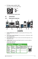
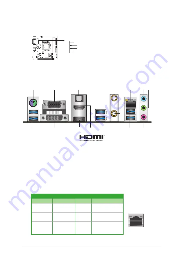
Rear panel connectors

LAN port

SPEED 

LED

ACT/LINK 

LED

Activity/Link LED

Speed LED

Status

Description

Status

Description

Off

No link

OFF

10Mbps connection

Orange

Linked

ORANGE 100Mbps connection

Orange 

(Blinking)

Data activity

GREEN

1Gbps connection

Orange 

(Blinking then 

steady)

Ready to 

wake up from 

S5 mode

_

_

2

5 6

4

7

8

8

1

8

11

10

3

12

9

1. 

PS/2 Mouse/Keyboard combo port.

 This port connects to a PS/2 mouse or PS/2 

keyboard.

2. 

Video Graphics Adapter (VGA) port. 

This 15-pin port is for a VGA monitor or other 

VGA-compatible devices.

3.


Optical S/PDIF Out port.

 This port connects an external audio output device via an 

optical S/PDIF cable.

4. 

LAN (RJ-45) port.

 These ports allow Gigabit connection to a Local Area Network 

(LAN) through a network hub.


LAN port LED indications

2. 

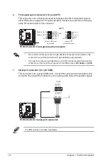
RTC Battery header (2-pin BATT_CON)

This connector is for the lithium CMOS battery.

H170I-PLUS D3

H170I-PLUS D3 RTC battery header

PIN 1

VBAT

GND

BATT_CON

Summary of Contents for H170I-PLUS D3

Page 1: ...Motherboard H170I PLUS D3 ...

Page 2: ...espective companies and are used only for identification or explanation and to the owners benefit without intent to infringe Offer to Provide Source Code of Certain Software This product contains copyrighted software that is licensed under the General Public License GPL under the Lesser General Public License Version LGPL and or other Free Open Source Software Licenses Such software in this produc...

Page 3: ...1 5 Wi Fi antenna installation 1 10 1 6 Expansion slots 1 11 1 7 Headers 1 12 1 8 Connectors 1 13 1 9 Onboard LEDs 1 22 1 10 Software support 1 23 Chapter 2 BIOS information 2 1 Managing and updating your BIOS 2 1 2 2 BIOS setup program 2 6 2 3 My Favorites 2 14 2 4 Main menu 2 16 2 5 Ai Tweaker menu 2 18 2 6 Advanced menu 2 27 2 7 Monitor menu 2 35 2 8 Boot menu 2 38 2 9 Tool menu 2 43 2 10 Exit ...

Page 4: ...erboard and adding components carefully read all the manuals that came with the package Before using the product ensure all cables are correctly connected and the power cables are not damaged If you detect any damage contact your dealer immediately To avoid short circuits keep paper clips screws and staples away from connectors slots sockets and circuitry Avoid dust humidity and temperature extrem...

Page 5: ...ks properly take note of the following symbols used throughout this manual DANGER WARNING Information to prevent injury to yourself when completing a task CAUTION Information to prevent damage to the components when completing a task IMPORTANT Instructions that you MUST follow to complete a task NOTE Tips and additional information to help you complete a task Typography Bold text Indicates a menu ...

Page 6: ...r to the Memory QVL for details Refer to www asus com for the Memory QVL Qualified Vendors List Graphics Integrated Graphics Processor Intel HD Graphics support Multi VGA output support DisplayPort HDMI DVI D D SUB port Supports DisplayPort with max resolution of 4096 x 2304 60Hz Supports HDMI with max resolution of 4096 x 2160 24Hz 2560 x 1600 60Hz 1920 x 1080 120Hz Supports DVI D with max resolu...

Page 7: ...ing Optical S PDIF out port at the back I O LAN Intel Gigabit LAN controller Anti Surge LANGuard Wireless Data Network Speedy Wi Fi 802 11 a b g n ac supports dual frequency band 2 4 5 GHz Bluetooth USB Intel H170 Express Chipset 8 x USB 3 0 2 0 ports 2 ports at mid board 6 ports at the back panel blue 4 x USB 2 0 1 1 ports 4 ports at mid boardl ASUS special features ASUS 5X PROTECTION ASUS DIGI V...

Page 8: ...nnel Audio I O ports Internal connectors 1 x 19 pin USB 3 0 2 0 connector supports additional 2 USB 3 0 2 0 ports 2 x USB 2 0 1 1 connectors support additional 4 USB 2 0 1 1 ports 1 x S PDIF out header 1 x System panel connector 1 x Front panel audio connector AAFP 4 x SATA 6 0 Gb s connectors gray 2 from SATA Express port 1 x M 2 Socket 3 for M Key type 2242 2260 2280 devices 1 x SATA Express con...

Page 9: ...Favorites Quick Note Last Modified log F12 PrintScreen and ASUS DRAM SPD Serial Presence Detect memory information Manageability WfM 2 0 DMI 3 0 WOL by PME PXE Support DVD Drivers ASUS utilities EZ Update Anti virus software OEM version Operating System Support Windows 10 Windows 8 1 Windows 7 Form factor Mini ITX form factor 6 7 x 6 7 17cm x 17cm Specifications are subject to change without notic...

Page 10: ...x ...

Page 11: ...onent ensure that the ATX power supply is switched off or the power cord is detached from the power supply Failure to do so may cause severe damage to the motherboard peripherals or components 1 2 Motherboard overview Before you install the motherboard study the configuration of your chassis to ensure that the motherboard fits Unplug the power cord before installing or removing the motherboard Fai...

Page 12: ...bit 240 pin module DDR3_DIMM_B1 64bit 240 pin module EATX_PWR AUDIO1 AAFP COM ASM 1442K BATT_CON CPU_FAN CHA_FAN1 CHA_FAN2 SATA6G_6 SB_PWR SATA6G_5 M 2 SOCKET3 Intel H170 SATAEXPRESS PCIEX16 CLRTC SPEAKER SPDIF_OUT I219V LAN1_USB3_34 KBMS_USB3_78 DVI VGA 128Mb BIOS LGA1151 USB3_12 USB910 F_PANEL USB1112 ATX12V TPM M 2 WIFI USB3_56 SPDIFO _HDMI _DP 1 2 7 8 9 2 6 1 13 12 15 14 3 7 11 10 16 17 4 5 ...

Page 13: ...nel connector 10 1 pin F_PANEL 1 21 7 Intel Z170 Serial ATA 6 0 Gb s connectors 7 pin SATA6G_3 6 SATAEXPRESS 1 15 8 USB 2 0 connectors 10 1 pin USB910 USB1112 1 16 9 USB 3 0 connector 20 1 pin USB3_12 1 16 10 Standby power LED SB_PWR 1 22 11 M 2 Socket 3 1 19 12 Clear RTC RAM 2 pin CLRTC 1 12 13 Digital audio connector 4 1 pin SPDIF_OUT 1 21 14 Front panel audio connector 10 1 pin AAFP 1 18 15 TPM...

Page 14: ...o the PnP cap socket contacts motherboard components Keep the cap after installing the motherboard ASUS will process Return Merchandise Authorization RMA requests only if the motherboard comes with the cap on the LGA1151 socket The product warranty does not cover damage to the socket contacts resulting from incorrect CPU installation removal or misplacement loss incorrect removal of the PnP cap H1...

Page 15: ...ASUS H170I PLUS D3 1 5 Top of CPU Bottom of CPU Bottom of CPU Top of CPU ...

Page 16: ...1 6 Chapter 1 Product introduction 3 4 A B B A To uninstall the CPU heatsink and fan assembly 2 1 To install the CPU heatsink and fan assembly 2 B A A B 1 ...

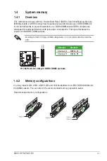
Page 17: ...pin DDR3 DIMM sockets DIMM_B1 DIMM_A1 1 4 System memory 1 4 1 Overview This motherboard comes with two Double Data Rate 3 DDR3 Dual Inline Memory Module DIMM sockets A DDR3 module has the same physical dimensions as a DDR2 DIMM but is notched differently to prevent installation on a DDR2 DIMM socket DDR3 modules are developed for better performance with less power consumption The figure illustrate...

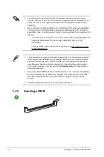
Page 18: ...or more on the motherboard For more details refer to the Microsoft support site at http support microsoft com kb 929605 en us The default memory operation frequency is dependent on its Serial Presence Detect SPD which is the standard way of accessing information from a memory module Under the default state some memory modules for overclocking may operate at a lower frequency than the vendor marked...

Page 19: ...ASUS H170I PLUS D3 1 9 2 3 To remove a DIMM B A ...

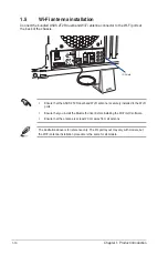
Page 20: ...re that the ASUS 2T2R dual band Wi Fi antenna is securely installed to the Wi Fi ports Ensure that you install the Bluetooth driver before installing the Wi Fi GO software Ensure that the antenna is at least 20 cm away from all persons The illustration above is for reference only The I O port layout may vary with models but the Wi Fi antenna installation procedure is the same for all models ...

Page 21: ...ard connector with the slot and press firmly until the card is completely seated on the slot 5 Secure the card to the chassis with the screw you removed earlier 6 Replace the system cover 1 6 2 Configuring an expansion card After installing the expansion card configure it by adjusting the software settings 1 Turn on the system and change the necessary BIOS settings if any See Chapter 2 for informa...

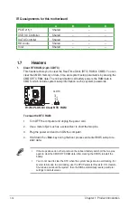
Page 22: ... Turn OFF the computer and unplug the power cord 2 Use a metal object such as a screwdriver to short the two pins 3 Plug the power cord and turn ON the computer 4 Hold down the Del key during the boot process and enter BIOS setup to re enter data If the steps above do not help remove the onboard battery and short the two pins again to clear the CMOS RTC RAM data After clearing the CMOS reinstall t...

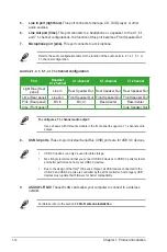
Page 23: ...12 9 1 PS 2 Mouse Keyboard combo port This port connects to a PS 2 mouse or PS 2 keyboard 2 Video Graphics Adapter VGA port This 15 pin port is for a VGA monitor or other VGA compatible devices 3 Optical S PDIF Out port This port connects an external audio output device via an optical S PDIF cable 4 LAN RJ 45 port These ports allow Gigabit connection to a Local Area Network LAN through a network h...

Page 24: ...er Out Front Speaker Out Front Speaker Out Pink Rear panel Mic In Mic In Bass Center Bass Center Lime Front panel Side Speaker Out To configure a 7 1 channel audio output Use a chassis with HD audio module in the front panel to support a 7 1 channel audio output 8 USB 3 0 ports These 9 pin Universal Serial Bus USB ports are for USB 3 0 devices USB 3 0 devices can only be used for data storage We s...

Page 25: ...ables If you installed Serial ATA hard disk drives you can create a RAID 0 1 5 and 10 configuration with the Intel Rapid Storage Technology through the onboard Intel H170 chipset These connectors are set to AHCI by default If you intend to create a Serial ATA RAID set using these connectors set the SATA Mode item in the BIOS to RAID Refer to section 2 6 3 PCH Storage Configuration for details Befo...

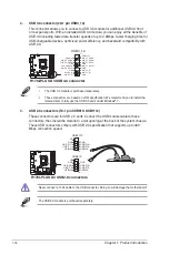
Page 26: ...pin USB910 USB1112 These connectors are for USB 2 0 ports Connect the USB module cable to these connectors then install the module to a slot opening at the back of the system chassis These USB connectors comply with USB 2 0 specification that supports up to 480 Mbps connection speed Never connect a 1394 cable to the USB connector Doing so will damage the motherboard The USB 2 0 module is purchased...

Page 27: ...e CPU_FAN connector supports the CPU fan of maximum 1A 12 W fan power The CPU_FAN and CHA_FAN connectors support the ASUS FAN Xpert 2 feature The chassis fan connectors support DC and PWM modes To set these fans to DC or PWM go to Advanced Mode Monitor Chassis Fan 1 2 Q Fan Control items in BIOS 5 Speaker connector 4 pin SPEAKER This 4 pin connector is for the chassis mounted system warning speake...

Page 28: ...udio module to this connector set the Front Panel Type item in the BIOS setup to HD Audio or AC97 7 Serial port connector 10 1 pin COM This connector is for a serial COM port Connect the serial port module cable to this connector then install the module to a slot opening at the back of the system chassis H170I PLUS D3 H170I PLUS D3 Front panel audio connector AAFP SENSE2_RETUR SENSE1_RETUR NC AGND...

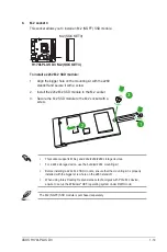
Page 29: ...t the mounting kit is properly installed with the bigger screw hole on the 2260 standoff When using Intel Desktop Responsiveness technologies with PCIe M 2 device ensure to set up the Windows UEFI operating system under RAID mode The M 2 NGFF SSD module is purchased separately 2 3 1 To install a 2242 M 2 SSD module 1 Align the bigger hole on the mounting kit with the 2260 standoff and secure it wi...

Page 30: ...f you are uncertain about the minimum power supply requirement for your system refer to the Recommended Power Supply Wattage Calculator at http support asus com PowerSupplyCalculator PSCalculator aspx SLanguage en us for details 9 ATX power connectors 24 pin EATXPWR 4 pin EATX12V These connectors are for ATX power supply plugs The power supply plugs are designed to fit these connectors in only one...

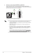
Page 31: ...ct the chassis power LED cable to this connector The system power LED lights up when you turn on the system power and blinks when the system is in sleep mode Hard disk drive activity LED 2 pin HDD_LED This 2 pin connector is for the HDD Activity LED Connect the HDD Activity LED cable to this connector The HDD LED lights up or flashes when data is read from or written to the HDD ATX power button so...

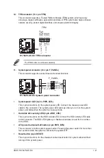
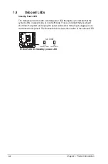
Page 32: ...e that the system is ON in sleep mode or in soft off mode This is a reminder that you should shut down the system and unplug the power cable before removing or plugging in any motherboard component The illustration below shows the location of the onboard LED H170I PLUS D3 H170I PLUS D3 Standby power LED SB_PWR ON Standby Power Powered Off OFF ...

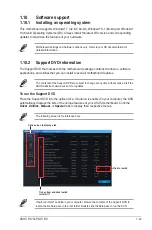
Page 33: ... install to avail all motherboard features The contents of the Support DVD are subject to change at any time without notice Visit the ASUS website at www asus com for updates To run the Support DVD Place the Support DVD into the optical drive If Autorun is enabled in your computer the DVD automatically displays the lists of the unique features of your ASUS motherboard Click the Driver Utilities Ma...

Page 34: ...1 24 Chapter 1 Product introduction ...

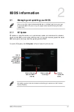
Page 35: ...ard s softwares drivers and the BIOS version easily With this utlity you can also manually update the saved BIOS and select a boot logo when the system goes into POST To launch EZ Update click EZ Update on the AI Suite 3 main menu bar Click to automatically update your motherboard s driver software and firmware Click to find and select the BIOS from file Click to select a boot logo Click to update...

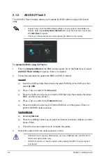
Page 36: ...a the Internet a Select by Internet b Press the Left Right arrow keys to select an Internet connection method and then press Enter c Follow the onscreen instructions to complete the update 3 Reboot the system when the update process is done ASUS EZ Flash 3 supports USB devices such as a USB flash disk with FAT 32 16 format and single partition only DO NOT shut down or reset the system while updati...

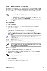
Page 37: ...tility reads the BIOS file and enters ASUS EZ Flash 3 utility automatically 4 The system requires you to enter BIOS Setup to recover BIOS settings To ensure system compatibility and stability we recommend that you press F5 to load default BIOS values DO NOT shut down or reset the system while updating the BIOS Doing so can cause system boot failure 2 1 4 ASUS BIOS Updater ASUS BIOS Updater allows ...

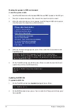
Page 38: ...from Drive C optical drive to Drive D USB flash drive ISOLINUX 3 20 2006 08 26 Copyright C 1994 2005 H Peter Anvin A Bootable DVD CD is detected Press ENTER to boot from the DVD CD If no key is pressed within 5 seconds the system will boot next priority device automatically boot Updating the BIOS file To update the BIOS file 1 On the FreeDOS prompt type bupdater pc g and press Enter 2 On the BIOS ...

Page 39: ...ile and press Enter 4 After the BIOS Updater checks the selected BIOS file select Yes to confirm the BIOS update Are you sure you want to update the BIOS Yes No The BIOS Backup feature is not supported due to security regulations 5 Select Yes then press Enter When BIOS update is done press ESC to exit BIOS Updater 6 Restart your computer DO NOT shut down or reset the system while updating the BIOS...

Page 40: ... you always shut down the system properly from the operating system The BIOS setup screens shown in this section are for reference purposes only and may not exactly match what you see on your screen Visit the ASUS website at www asus com to download the latest BIOS file for this motherboard Ensure that a USB mouse is connected to your motherboard if you want to use the mouse to control the BIOS se...

Page 41: ...epending on the devices you installed to the system Saves the changes and resets the system Selects the display language of the BIOS setup program Displays the CPU motherboard temperature CPU voltage output CPU chassis fan speed and SATA information Displays the system properties of the selected mode Click or to switch EZ System Tuning modes Displays the Advanced mode menus Selects the boot device...

Page 42: ...tions for the detailed configurations To access the EZ Mode click EzMode F7 or press F7 Configuration fields Menu bar General help Sub menu item Menu items Scroll bar Last modified settings Language Hot Keys MyFavorite Q Fan control EZ Tuning Wizard Goes back to EZ Mode Displays the CPU motherboard temperature CPU and memory voltage output Quick Note Search on FAQs 2 8 Chapter 2 Getting started ...

Page 43: ... This button above the menu bar displays the current settings of your fans Use this button to manually tweak the fans to your desired settings Refer to section 2 2 3 QFan Control for more information EZ Tuning Wizard F11 This button above the menu bar allows you to view and tweak the overclocking settings of your system It also allows you to change the motherboard s SATA mode from AHCI to RAID mod...

Page 44: ...oll bar appears on the right side of a menu screen when there are items that do not fit on the screen Press the Up Down arrow keys or Page Up Page Down keys to display the other items on the screen General help At the top right corner of the menu screen is a brief description of the selected item Use F12 key to capture the BIOS screen and save it to the removable storage device Configuration field...

Page 45: ...file or manually configure the operating speed of your CPU and chassis fans Click to select a fan to be configured Click to undo the changes Click to apply the fan setting Click to go back to main menu Select a profile to apply to your fans ASUS H170I PLUS D3 2 11 ...

Page 46: ... speed To configure your fans 1 Select the fan that you want to configure and to view its current status 2 Click and drag the speed points to adjust the fans operating speed 3 Click Apply to save the changes then click Exit ESC Speed points Click to manually configure your fans 2 12 Chapter 2 Getting started ...

Page 47: ...2 2 4 EZ Tuning Wizard EZ Tuning Wizard allows you to easily set your SATA HDD SSD to RAID mode ASUS H170I PLUS D3 2 13 ...

Page 48: ...2 3 My Favorites MyFavorites is your personal space where you can easily save and access your favorite BIOS items 2 14 Chapter 2 Getting started ...

Page 49: ...the submenu that you want to save as favorite from the submenu panel and click You cannot add the following items to My Favorite items Items with submenu options User managed items such as language and boot order Configuration items such as Memory SPD Information system time and date 4 Click Exit ESC or press esc key to close Setup Tree Map screen 5 Go to My Favorites menu to view the saved BIOS i...

Page 50: ...you to change the system security settings If you have forgotten your BIOS password erase the CMOS Real Time Clock RTC RAM to clear the BIOS password See section 1 6 Headers for information on how to erase the RTC RAM The Administrator or User Password items on top of the screen show the default Not Installed After you set a password these items show Installed Administrator Password If you have se...

Page 51: ...talled User Password If you have set a user password you must enter the user password for accessing the system The User Password item on top of the screen shows the default Not Installed After you set a password this item shows Installed To set a user password 1 Select the User Password item and press Enter 2 From the Create New Password box key in a password then press Enter 3 Confirm the passwor...

Page 52: ...this section vary depending on the CPU and DIMM model you installed on the motherboard Scroll down to display other BIOS items Target CPU Turbo Mode Frequency xxxxMHz Displays the target CPU Turbo Mode frequency Target DRAM Frequency xxxxMHz Displays the target DRAM frequency Target Cache Frequency xxxxMHz Displays the target Cache frequency Target CPU Graphics Frequency xxxxMHz Displays the targe...

Page 53: ...mit Auto Select Auto to apply the CPU default Turbo Ratio setting or manually assign a 3 Core Limit value that must be higher than or equal to the 4 Core Ratio Limit If you assign a value for 3 Core Ratio Limit do not set the 1 Core Ratio Limit and 2 Core Ratio Limit to Auto 4 Core Ratio Limit Auto Select Auto to apply the CPU default Turbo Ratio setting or manually assign a 4 Core Limit value tha...

Page 54: ...age regulator Configuration options Auto Disabled Enabled 2 5 8 DRAM Timing Control The subitems in this menu allow you to set the DRAM timing control features Use the and keys to adjust the value To restore the default setting type auto using the keyboard and press the Enter key Changing the values in this menu may cause the system to become unstable If this happens revert to the default settings...

Page 55: ...ows you to set the power phase control of the CPU Configuration options Auto Standard Optimized Extreme Power Phase Response DO NOT remove the thermal module when setting this item to Power Phase Response The thermal conditions should be monitored The following item appears only when you set the CPU Power Phase Control to Power Phase Response Power Phase Response Fast This item allows you to set a...

Page 56: ...hermal conditions of every component s phase T Probe Select to maintain the VRM thermal balance Extreme Select to maintain the current VRM balance CPU Power Phase Control Auto This item allows you to set the power phase control of the CPU Configuration options Auto Standard Optimized Extreme CPU Graphics Load Line Calibration Auto Load line is defined by Intel VRM specification and affects GT powe...

Page 57: ... to maintain the current VRM balance CPU Graphics Power Phase Control Auto This item allows you to set the power phase control of the CPU Configuration options Auto Standard Optimized Extreme Power Phase Response DO NOT remove the thermal module when setting this item to Power Phase Response The thermal conditions should be monitored The following item appears only when you set the CPU Power Phase...

Page 58: ... range from 1 W to 4096 W IA AC Load Line Auto This item allows you to set the AC loadline defined in 1 100 mOhms Use the and keys to adjust the value Configuration options Auto 0 01 62 49 IA DC Load Line Auto This item allows you to set the DC loadline defined in 1 100 mOhms Use the and keys to adjust the value Configuration options Auto 0 01 62 49 2 5 11 CPU Core Cache Current Limit Max Auto All...

Page 59: ...ge by a negative value CPU Core Voltage Offset Use the or keys to adjust the value The values range from 0 001V to 0 999V with a 0 001V interval 2 5 17 DRAM Voltage Auto This item allows you to set the voltage for the DRAM Use the and keys to adjust the value The values range from 1 000V to 2 000V with a 0 005 interval 2 5 18 CPU System Agent Voltage Auto This item allows you to set the voltage fo...

Page 60: ...tings 2 5 21 DRAM REF Voltage Control Auto The subitems in this menu allows you to set the DRAM reference voltage on the control lines from the memory bus You can use the or keys to adjust the value The values range from 0 39500V to 0 63000V with a 0 00500V interval DRAM CTRL REF Voltage Auto This item allows you to set the DRAM reference voltage on the control lines from the memory bus You can us...

Page 61: ...wing the operating system to schedule two threads or processes simultaneously Configuration options Disabled Enabled Active Processor Cores All This item allows you to select the number of CPU cores to activate in each processor package Configuration options All 1 2 3 For some CPU types only All and 1 appear Intel Virtualization Technology Disabled When set to Enabled a VMM can utilize the additio...

Page 62: ... of the CPU states Configuration options Auto Disabled Enabled The following items appear only when you set the CPU C States to Enabled Enhanced C states Enabled This item allows your CPU to reduce power consumption when the system is in idle mode Configuration options Enabled Disabled CPU C3 Report Enabled This item allows you to disable or enable the CPU C3 report to the operating system Configu...

Page 63: ...m allows you to select the ASPM state for energy saving conditions Configuration options Disabled L0s L1 L0sL1 Auto SA PCI Express options DMI Link ASPM Control Disabled This item allows you to control the Active State Power Management on both CPU and PCH platform controller hub Both DMI link ASPM control items of the CPU and PCH sides must be enabled for the ASPM to take effect Configuration opti...

Page 64: ... Configuration options Auto Gen1 Gen2 Gen3 PEG Port Configuration Allows you to configure the PEG Port settings Enable Root Port Enabled Allows you to configure the root port Configuration options Disabled Enabled Auto PCIEx16_1 Link Speed Auto Allows you to configure the PCIEx16 speed for slot 1 Configuration options Auto Gen1 Gen2 Gen3 Memory Configuration Allows you to configure the memory conf...

Page 65: ...owing the drive to internally optimize the order of commands RAID Set to RAID Mode when you want to create a RAID configuration from the SATA hard disk drives M 2 PCIE Storage RAID Support Enabled Enable this item to remap PCIE port to SATA for RAID support Only six 6 SATA ports will remain when enabling this item Configuration options Disabled Enabled CR 1 Remap Port Selection Disabled This item ...

Page 66: ...port USB Single Port Control This item allows you to enable or disable the individual USB ports Refer to section 1 2 3 Motherboard layout for the location of the USB ports 2 6 7 Onboard Devices Configuration HD Audio Controller Enabled This item allows you to use the Azalia High Definition Audio Controller Configuration options Disabled Enabled The following items appear only when you set the HD A...

Page 67: ... state and is not doing any computing tasks Disabled Disables this function Serial Port Configuration The sub items in this menu allow you to set the serial port configuration Serial Port Enabled Allows you to enable or disable the serial port COM Configuration options Enabled Disabled Change Settings IO 3F8h IRQ 4 This item appears only when you set the Serial Port to Enabled and allows you to se...

Page 68: ...me Clock to generate a wake event and configure the RTC alarm date When enabled you can set the days hours minutes or seconds to schedule an RTC alarm date Configuration options Disabled Enabled 2 6 9 Network Stack Configuration Network Stack Disabled This item allows user to disable or enable the UEFI network stack Configuration options Disabled Enabled The following two items appear only when yo...

Page 69: ...is fan 1 2 speeds in rotations per minute RPM If the fan is not connected to the motherboard the field shows N A Select Ignore if you do not wish to display the detected speed 2 7 3 CPU Core Voltage 3 3V Voltage 5V Voltage 12V Voltage The onboard hardware monitor automatically detects the voltage output through the onboard voltage regulators Select Ignore if you do not want to detect this item 2 7...

Page 70: ... The following four items appear only when you set CPU Fan Profile to Manual CPU Upper Temperature 70 Use the or keys to adjust the upper limit of the CPU temperature The values range from 25 C to 75 C CPU Fan Max Duty Cycle 100 Use the or keys to adjust the maximum CPU fan duty cycle The values range from 20 to 100 When the CPU temperature reaches the upper limit the CPU fan operates at the maxim...

Page 71: ...rol feature and allows you to set the appropriate performance level of the chassis fan 1 2 3 4 Standard Sets to Standard to make the chassis fan automatically adjust depending on the chassis temperature Silent Sets to Silent to minimize the fan speed for quiet chassis fan operation Turbo Sets to Turbo to achieve maximum chassis fan speed Manual Sets to Manual to assign detailed fan speed control p...

Page 72: ...to enable or disable the Anti Surge function Configuration options Disabled Enabled 2 8 Boot menu The Boot menu items allow you to change the system boot options Scroll down to display the other BIOS items 2 8 1 Fast Boot Enabled Enabled Select to accelerate the boot speed Disabled Select to go back to normal boot speed The following item appears only when you set Fast Boot to Enabled Next Boot af...

Page 73: ...u to enable or disable power on state of the NumLock Configuration options Disabled Enabled 2 8 4 Wait for F1 If Error Enabled When this item is set to Enabled the system waits for the F1 key to be pressed when error occurs Configuration options Disabled Enabled 2 8 5 Option ROM Messages Enabled Enabled The third party ROM messages will be displayed during POST Disabled Disables the ROM messages a...

Page 74: ...you to select the type of storage devices that you want to launch Configuration options Both Legacy OpROM first Both UEFI first Legacy OpROM first UEFI driver first Ignore Boot from PCI E PCI Expansion Devices Legacy OpROM first Allows you to select the type of PCIe PCI expansion devices that you want to launch Configuration options Legacy OpROM first UEFI driver first 2 8 9 Secure Boot Allows you...

Page 75: ...e the PK is deleted all the system s Secure Boot keys will not be active Load Default PK Select Yes to load the system default PK or select No to load a downloaded PK from a USB storage device The PK file must be formatted as a UEFI variable structure with time based authenticated variable KEK Management The KEK Key exchange Key or Key Enrollment Key manages the Signature database db and Revoked S...

Page 76: ...variable structure with time based authenticated variable UEFI executable files include UEFI boot devices drivers and applications dbx Management The dbx Revoked Signature database lists the forbidden images of db items that are no longer trusted and cannot be loaded Delete the dbx Allows you to delete the DBX file from your system Doing so may expose the system to security threats Load Default db...

Page 77: ...ds on the number of devices installed in the system Click an item to start booting from the selected device 2 9 Tool menu The Tool menu items allow you to configure options for special functions Select an item then press Enter to display the submenu 2 9 1 ASUS EZ Flash 3 Utility Allows you to run ASUS EZ Flash 3 Press Enter to launch the ASUS EZ Flash 2 screen For more details see section ASUS EZ ...

Page 78: ...e to eight press Enter and then select Yes Load Save Profile from to USB Drive This item allows you to load or save profile from your USB drive load and save profile to your USB drive 2 9 4 ASUS SPD Information DIMM Slot number DIMM_A1 Displays the Serial Presence Detect SPD information of the DIMM module installed on the selected slot Configuration options DIMM_A1 DIMM_B1 2 10 Exit menu The Exit ...

Page 79: ...Select OK to save changes and exit Discard Changes Exit This option allows you to exit the Setup program without saving your changes When you select this option or if you press Esc a confirmation window appears Select OK to discard changes and exit Launch EFI Shell from USB drives This option allows you to attempt to launch the EFI Shell application shellx64 efi from one of the available USB devic...

Page 80: ...2 46 Chapter 2 Getting started ...

Page 81: ... that to which the receiver is connected Consult the dealer or an experienced radio TV technician for help The use of shielded cables for connection of the monitor to the graphics card is required to assure compliance with FCC regulations Changes or modifications to this unit not expressly approved by the party responsible for compliance could void the user s authority to operate this equipment IC...

Page 82: ...REACH website at http csr asus com english REACH htm DO NOT throw the motherboard in municipal waste This product has been designed to enable proper reuse of parts and recycling This symbol of the crossed out wheeled bin indicates that the product electrical and electronic equipment should not be placed in municipal waste Check local regulations for disposal of electronic products DO NOT throw the...

Page 83: ...America Address 800 Corporate Way Fremont CA 94539 USA Telephone 1 510 739 3777 Fax 1 510 608 4555 Web site http www asus com us Technical Support Support fax 1 812 284 0883 General support 1 812 282 2787 Online support http www service asus com ASUS COMPUTER GmbH Germany and Austria Address Harkort Str 21 23 D 40880 Ratingen Germany Fax 49 2102 959931 Web site http www asus com de Online contact ...

Page 84: ...EN 302 326 2 V1 2 2 2007 06 EN 302 326 3 V1 3 1 2007 09 EN 301 357 2 V1 4 1 2008 11 EN 302 291 1 V1 1 1 2005 07 EN 302 291 2 V1 1 1 2005 07 2006 95 EC LVD Directive EN 60950 1 A12 2011 EN 60065 2002 A12 2011 2009 125 EC ErP Directive Regulation EC No 1275 2008 Regulation EC No 642 2009 Regulation EC No 278 2009 Regulation EC No 617 2013 2011 65 EU RoHS Directive Ver 140331 CE marking Declaration D...

Reviews: