


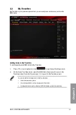


ASUS CROSSBLADE RANGER
3-13
Chapter 3
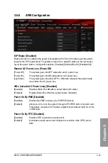
DRAM Power Phase Control [Optimized]
[Optimized]
Loads the ASUS optimized phase tuning profile.
[Extreme]
Proceeds to the full phase mode.
CPU Voltage [Offset Mode]
[Manual Mode] Allows you to set a fixed CPU voltage.
[Offset Mode]
Allows you to set the Offset voltage.
CPU Offset Mode Sign [+]
This item appears only when you set the
CPU Voltage
item to [Offset Mode].
[+]
To offset the voltage by a positive value.
[–]
To offset the voltage by a negative value.
CPU Offset Voltage [Auto]
This item appears only when you set the
CPU Voltage
item to [Offset Mode] and
allows you to set the Offset voltage. The values range from 0.00625V to 0.500V with a
0.00625V interval.
CPU Manual Voltage [Auto]
This item appears only when you set the
CPU Voltage
item to [Manual Mode] and
allows you to set a fixed CPU voltage. The values range from 0.800V to 1.900V with a
0.00625V interval.
Refer to the CPU documentation before setting the CPU voltage. Setting a high voltage
may damage the CPU permanently, and setting a low voltage may make the system
unstable.
VDDNB Offset Mode Sign [+]
This item appears only when you set the
CPU Voltage
item to [Offset Mode].
[+]
To offset the voltage by a positive value.
[–]
To offset the voltage by a negative value.
VDDNB Offset Voltage [Auto]
This item appears only when you set the
CPU Voltage
item to [Offset Mode] and
allows you to set the VDDNB Offset voltage. The values range from 0.00625V to
0.500V with a 0.00625V interval.
VDDNB Manual Voltage [Auto]
This item appears only when you set the
CPU Voltage
item to [Manual Mode] and
allows you to set a fixed VDDNB voltage. The values range from 0.800V to 1.900V with
a 0.00625V interval.
DRAM Voltage [Auto]
Allows you to set the DRAM voltage. The values range from 1.35V to 2.135V with a 0.005V
interval.
Summary of Contents for Crossblade Ranger
Page 1: ...Motherboard CROSSBLADE RANGER ...
Page 61: ...ASUS CROSSBLADE RANGER 2 5 Chapter 2 To uninstall the APU heatsink and fan assembly 5 3 1 4 2 ...
Page 62: ...2 6 Chapter 2 Basic Installation Chapter 2 1 2 3 To remove a DIMM 2 1 4 DIMM installation B A ...
Page 63: ...ASUS CROSSBLADE RANGER 2 7 Chapter 2 2 1 5 ATX Power connection 1 2 OR ...
Page 64: ...2 8 Chapter 2 Basic Installation Chapter 2 2 1 6 SATA device connection 2 OR 1 ...
Page 72: ...2 16 Chapter 2 Basic Installation Chapter 2 Connect to 7 1 channel Speakers ...
Page 74: ...2 18 Chapter 2 Basic Installation Chapter 2 ...
Page 121: ...ASUS CROSSBLADE RANGER 3 47 Chapter 3 ...
Page 155: ...4 34 Chapter 4 Software support Chapter 4 Function Keys Shortcut ...
Page 165: ...4 44 Chapter 4 Software support Chapter 4 ...
Page 177: ...A 6 Appendices Appendices ...