


INVENT3D Printer Kit Disassembly Instructions
AST2 © 10/26/16 18
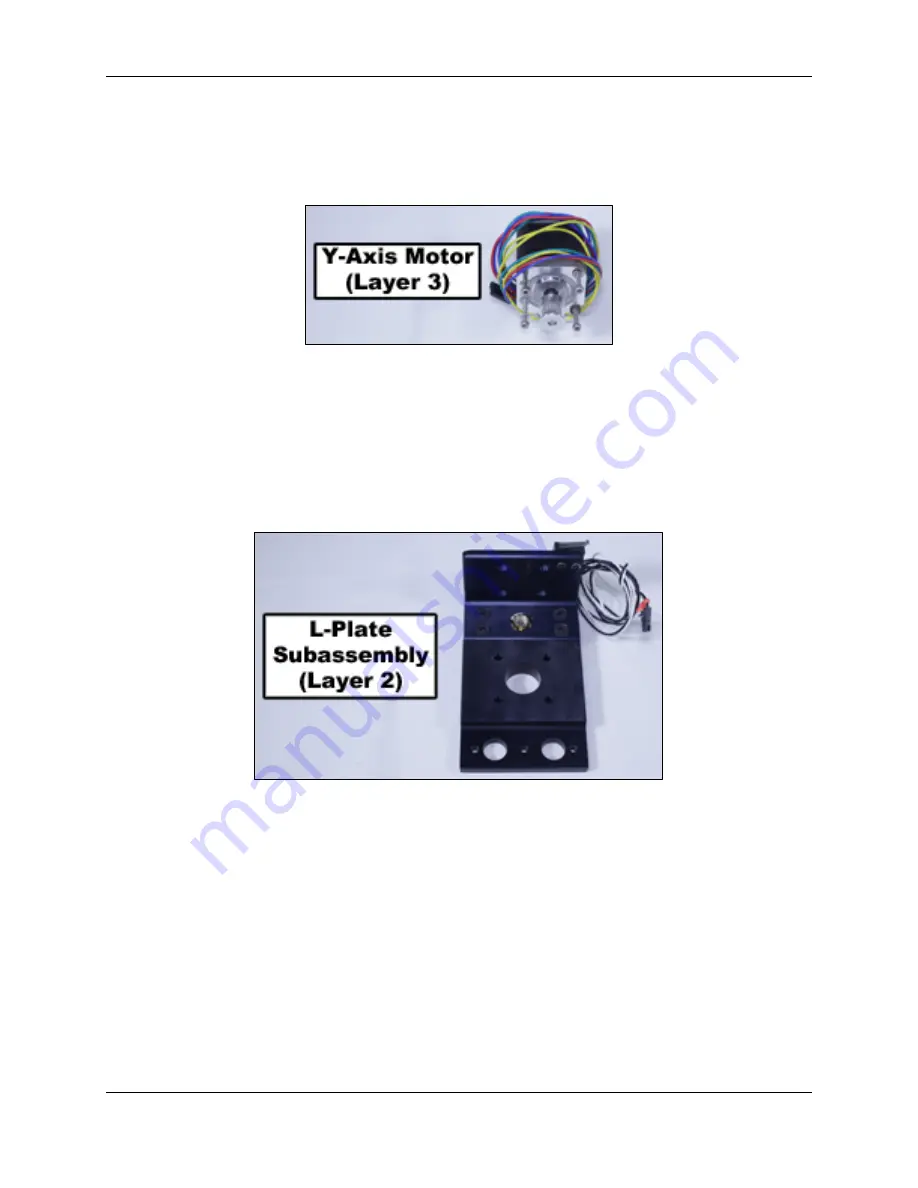
27.
Remove y-axis motor and reinsert mounting hardware into the top of the motor. Coil
wire around base of motor and pass plug end under the coil to prevent from unraveling.
Store y-axis motor in location as shown in Case Layer Drawing 3.
28.
Remove four flat head screws that attach L-plate to the z-axis carriage. Rotate lead
screw to remove L-plate. Replace flat head screws in z-axis carriage. Coil z-axis limit
switch wire and place plug end through coil to hold in place. Store L-plate in location as
shown in Case Layer Drawing 2.


