background image

22

7300 Series

Installation Instructions

Multi-Point Lock

A8270A  02/20

Copyright © 2017, 2019, 2020 SARGENT Manufacturing Company. All rights reserved. Reproduction in whole or in 
part without the express written permission of SARGENT Manufacturing Company is prohibited.

1-800-727-5477 • www.sargentlock.com

5 Addendum 

(cont.)

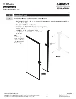
Mortise Reinforcer and Mortise Lock Installation

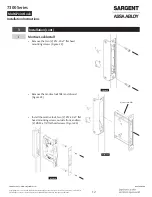
•  Remove the two (2) #12-24x1" flat head LBC mounting screws that are securing the lockbody case in 

the door. (Figure 50) 

•  Place mortise reinforcer into the door.

•  Reinstall two (2) #12-24x1" flat head LBC mounting screws

(DO NOT FORCE).

•  Install two (2) #12x1/4" self tapping screws 

through mortise reinforcer into the face of the door.
(Figure 51)

Note:

Reinforcer lip 
belongs on the side 
of the door that has 
a special cutout at 
the door edge.


Figure 50 


Figure 51

Summary of Contents for Sargent 7300 Series

Page 1: ...ring Company is prohibited 1 800 727 5477 www sargentlock com WARNING This product can expose you to lead which is known to the state of California to cause cancer and birth defects or other reproductive harm For more information go to www P65warnings ca gov Important The latches rods and cassette are pre installed This product must be installed by a factory trained technician 7300 Series Multi Po...

Page 2: ...Access Control EAC Shield 5 b Tools Required for Dogging Indicator Option 5 3 Installation 6 a Check Door 6 b Door Installation 6 c Install Top Strike into Door Frame 6 d Install Center Strike into Door Frame 7 e Remove Retractor Inserts 7 f Check Latches uninstalled 7 g Install Bottom Strike 8 h Top and Bottom Latch Adjustment 10 i Mortise Lock Install 12 j Final Mortise Lock and Trim Installatio...

Page 3: ...rohibited 1 800 727 5477 www sargentlock com 5 Addendum 16 a Check Door 16 b Place Door Horizontal on Sawhorse 16 c Install Lockbody Cassette LBC 17 d Latch Rod Guides 17 e Feed Top Rod into Door 18 f Align with Lockbody Cassette LBC 18 g Troubleshoot Latch Installation 19 h Correct Rod Installation Check 19 i Secure Top Latch 20 j Tighten Set Screw 20 k Bottom Latch Installation 21 l Check Latch ...

Page 4: ...ackage Contents Part Number Description 1 82 5342 Multipoint cassette 2 82 5345 Trim mounting screw pack 3 82 5346 Top bottom case mounting screw pack 4 82 5347 Top strike pack 5 82 5348 Bottom strike pack 6 82 5349 Mortise mounting reinforcement pack 7 82 5350 Center strike pack 8 188 Dogging indicator includes item 11 specify finish 9 82 5386 Top case and rod assembly specify door size 10 82 538...

Page 5: ...ring Company is prohibited 1 800 727 5477 www sargentlock com 2 Tools Required Tape measure Hammer Flashlight 1 8 Allen supplied 3 32 Allen supplied 5 32 Allen Drill 1 8 Masonry drill bit 3 Phillips bit Slotted screwdriver 1 2 3 Phillips head screwdrivers Chisel 3 8 Anchor set a Tools Required for Electronic Access Control EAC Shield 29 Drill bit 136 8 32 Tap b Tools Required for Dogging Indicator...

Page 6: ...nd hand for opening Correctly prepared to Template 4740 IMPORTANT If measurement is incorrect DO NOT PROCEED WITH INSTALLATION Contact door manufacturer Figure 1 b Door Installation Hang the door on the frame IMPORTANT If the door rubs along the floor do not complete this installation Contact door manufacturer c Install Top Strike into Door Frame Remove the strike filler plate and screws and disca...

Page 7: ...cont d Install Center Strike into Door Frame Install two 2 20 socket cap flat head screws Figure 3 e Remove Retractor Inserts WARNING The door now has the ability to latch Figure 4 f Check Latches uninstalled Insert the uninstalled outside mortise trim and rotate to verify the top and bottom latches retract flush with the door Do not install mortise trim at this time Figure 5 Move the top strike b...

Page 8: ...w sargentlock com 3 Installation cont g Install Bottom Strike Close the door and mark the location of the bottom bolt 3 8 MAX Bottom of door to floor Figure 7 Open the door and place the strike over the bottom bolt location Mark the location of the bottom strike pocket and hole locations Figure 7 Note The strike is not symetric Install as shown If needed the strike can later be rotated to increase...

Page 9: ...NT Use a vacuum or compressed air to clear holes of debris Figure 10 Cross Sectional View Flush Mount Figure 11 Surface Mount Figure 12 Drill two 2 3 8 diameter holes by 2 1 4 deep Chisel the bottom strike pocket 1 deep to ensure the bolt has full projection Figure 12 IMPORTANT Use a vacuum or compressed air to clear holes of debris Figure 13 Cross Sectional View Surface Mount Figure 14 1 2 1 4 Fi...

Page 10: ...learance between the top and bottom bolts and strikes Figure 15 Note If both measurements equal 1 16 proceed to Step 3i otherwise proceed with Step 3h as follows Remove the mortise filler cap and discard Figure 16 Retract the latches by roting the lever and opening the door Figure 17 Figure 17 Using the supplied 1 8 Allen wrench loosen the set screw 1 4 turn maximum This allows hex rods to rotate ...

Page 11: ...worm gears according to the directions below Figure 19 Bolt to strike clearance should equal 1 16 This sets the bolt projection Figure 20 Note Ten 10 turns equals approximately 1 16 Rotate the top counterclockwise to project the bolt clockwise to retract the bolt Rotate the bottom counterclockwise to retract the bolt clockwise to project the bolt Note Latches have bottomed if worm gears click Tigh...

Page 12: ...n of SARGENT Manufacturing Company is prohibited 1 800 727 5477 www sargentlock com 3 Installation cont i Mortise Lock Install Remove the two 2 12 24 x1 flat head mounting screws Figure 22 Remove the mortise lock filler and discard Figure 23 Install the mortise lock two 2 12 24 x1 flat head mounting screws outside front and two 2 8 32 x1 4 flat head screws Figure 24 Figure 24 Figure 22 Mortise Loc...

Page 13: ...ntroller Installation Follow supplied EAC Installation Instructions if applicable l Key Override with Deadbolt Function Operation Check Verify hand and bevel of door to determine direction to rotate key and lever Stand on outside of locked door when determining door hand Figure 26 Left Hand Hinges Left Open Inward LH Right Hand Hinges Right Open Inward RH Left Hand Reverse Bevel Hinges Left Open O...

Page 14: ...ptional Installation a Dogging Indicator Installation Ensure the door is latched and all bolts are projected Place the plastic field template on the pin in the top rod through the oval cut out in the door Figure 27 Figure 27 Front View Side View Pin Using a 7 drill bit drill two 2 holes completely through the door making sure the drill remains square to the face of the door Figure 28 Figure 28 Cou...

Page 15: ...gging Indicator Installation cont Install the indicator on the inside of the door using supplied 10 24 x 2 oval head screws Make sure the control fingers grab the top rod pin as shown Figure 30 Figure 30 Side View Pin Control Fingers Check for proper operation Rotate the lever until the indicator window shows a single latch point Figure 31 Figure 31 Single Latch Point 3 Latch Points Indicator Wind...

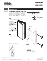
Page 16: ...e for pre installed hardware latches and cassette The following steps are for ease of reference as they have been completed in advance by the door manufacturer a Check Door Verify the door is Correct size and hand for opening Correctly prepared to Template 4740 Figure 32 IMPORTANT If measurement is incorrect DO NOT PROCEED WITH INSTALLATION Contact door manufacturer b Place Door Horizontal on Sawh...

Page 17: ...orm gears to align slots in the LBC gears to the orientation shown Figure 34 Alignment is needed for proper installation of the rod guide Step 3h Slide the LBC into the door case and secure with two 2 12 24x1 flat head screws Figure 35 d Latch Rod Guides Rod guides help installation by directing the rod into location in the LBC within the door cavity Pull rod guides away from latches on both rods ...

Page 18: ...ide so the rod guide tab faces up Slide the rod assembly into the door Make sure the rod guide remains in the correct orientation with the guide tab facing up Figure 37 f Align with Lockbody Cassette LBC When approaching the LBC slightly elevate the rod and slide the guide tab on outer diameter of the LBC gear Figure 38 Figure 38 To align the hex of rod with the hex of the LBC gear fit the rod gui...

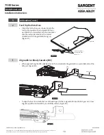
Page 19: ...tlock com 5 Addendum cont g Troubleshoot Latch Installation If the latch will not fully seat in the door rod or rod guide is not aligned properly with LBC gear Figure 40 h Correct Rod Installation Check Be certain a portion of the red end of the rod can be seen in the LBC viewing window and set screw is in the location shown Figure 41 Figure 40 REPEAT Step 6E to align REPEAT Step 6E to align Rod G...

Page 20: ...77 www sargentlock com 5 Addendum cont i Secure Top Latch Install four 4 10 24 oval head screws on the face of the door Figure 42 Install six 6 1 4 20 flat head screws in the top edge of the door Figure 43 Note Do not fully tighten until all screws are installed j Tighten Set Screw Using the supplied 1 8 Allen wrench tighten the set screw to secure the rod to the LBC Figure 44 IMPORTANT Latches wi...

Page 21: ...Installation REPEAT Steps 5e through 5k to install bottom latch Figure 45 l Check Latch Remove the bolt retainer clips from the top and bottom latch assemblies Figure 46 Insert mortise trim in the door prep and cassette and rotate to verify latches fully retract Figure 47 Confirm the set screw moves from circle to circle in the LBC viewing window Figure 48 Do not install the mortise lock at this t...

Page 22: ... Addendum cont m Mortise Reinforcer and Mortise Lock Installation Remove the two 2 12 24x1 flat head LBC mounting screws that are securing the lockbody case in the door Figure 50 Place mortise reinforcer into the door Reinstall two 2 12 24x1 flat head LBC mounting screws DO NOT FORCE Install two 2 12x1 4 self tapping screws through mortise reinforcer into the face of the door Figure 51 Note Reinfo...

Page 23: ...int Lock A8270A 02 20 Copyright 2017 2019 2020 SARGENT Manufacturing Company All rights reserved Reproduction in whole or in part without the express written permission of SARGENT Manufacturing Company is prohibited 1 800 727 5477 www sargentlock com ...

Page 24: ...tions The company s customer base includes commercial construction institutional and industrial markets Copyright 2017 2019 2020 SARGENT Manufacturing Company All rights reserved Reproduction in whole or in part without the express written permission of SARGENT Manufacturing Company is prohibited SARGENT Manufacturing Company 100 Sargent Drive New Haven CT 06511 USA 800 727 5477 www sargentlock co...

Reviews: